
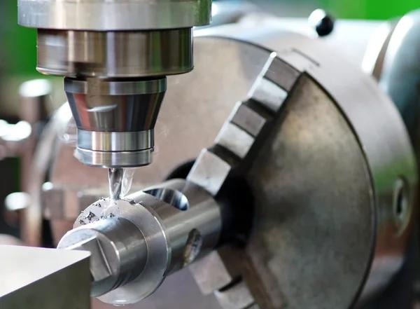
Rapid prototyping CNC milling is a machining approach built for product development and design verification. Instead of committing to tooling, it uses three-, four-, or five-axis milling to cut a solid blank directly from a CAD model, producing a high-precision prototype in a short time. It serves design checks, structural tests, appearance approval, and small trial runs.
Because no mold is needed, rapid prototyping CNC milling supports many materials, from aluminum and stainless steel to brass, ABS, POM, and nylon. Startups, design studios, and engineering teams use it to verify that a design works before the cost of a production commitment.

What Is Rapid Prototyping CNC Milling?
Rapid prototyping CNC milling is the use of computer-controlled milling to make prototype parts quickly and accurately. A model or drawing defines the geometry, the machine removes material from a blank, and the result is a physical part that behaves like the intended production component.
It differs from additive processes in that it starts from solid stock and removes material. That gives it better surface quality and more predictable mechanical properties, which is why it is chosen for functional prototypes. It differs from mass production in that it needs no dedicated tooling, so it can be changed between batches.
Why Use Rapid Prototyping CNC Milling?
The value of rapid prototyping CNC milling lies in reducing the cost of being wrong. A design flaw found in a prototype is cheap to fix; the same flaw found after tooling is committed is expensive. Making a real part early lets a team test fit, function, and assembly before those decisions are locked in.
It also produces parts that represent production behavior. A milled prototype in the intended material will machine, bend, and load much like the final part, unlike a printed approximation. For products that will eventually be machined, rapid prototyping CNC milling is the most direct validation route.
Materials for Rapid Prototyping CNC Milling
Material choice should reflect what the prototype must prove. Common options include:
- Aluminum alloys: fast to machine, corrosion resistant, good for general structures and housings.
- Stainless steel: strong and corrosion resistant, slower to cut but suitable for demanding parts.
- Brass and copper: good machinability and useful for electrical or decorative components.
- Titanium and magnesium: high strength-to-weight ratios for aerospace and specialized uses.
- Engineering plastics: ABS, POM, PC, nylon, acrylic, and PEEK for lightweight or insulating parts.
Using the final material in the prototype gives the most useful result. If cost or lead time forces a substitute, note the difference so the test result is interpreted correctly. Our guide on material substitution in machined parts explains why a similar-looking grade may not behave the same.
From Rapid Prototyping CNC Milling to Production
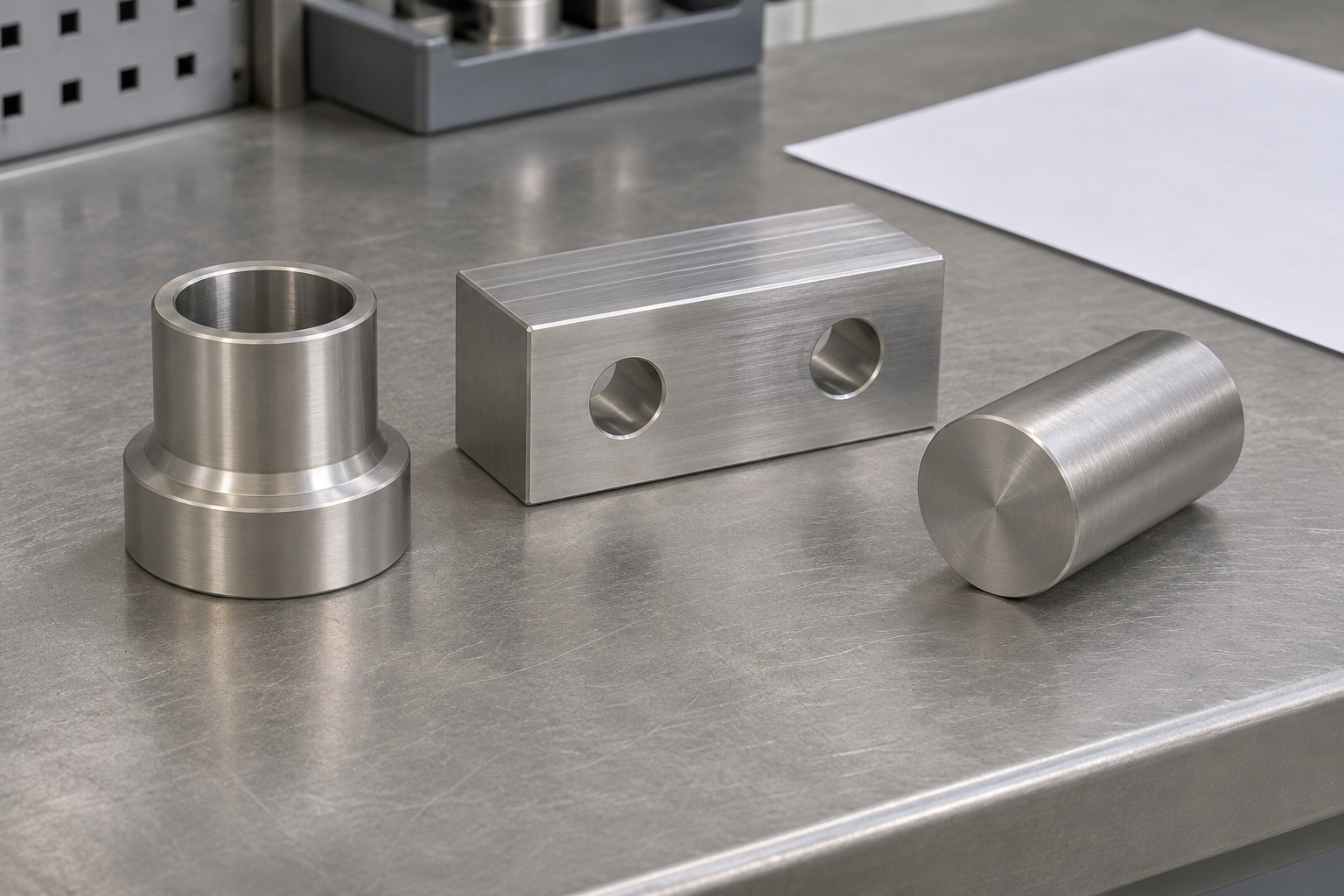
A prototype is rarely the end goal. Once the design is verified, the same rapid prototyping CNC milling route can often scale to small and medium volumes without changing the basic process. Because the geometry and inspection criteria are already proven, the transition is simpler than switching to a new method.
Keep the drawing revision, material grade, datum scheme, and inspection results together. When the order grows, the supplier can quote against that package rather than reinterpreting the design. If the product eventually moves to molding or casting, the milled prototypes still validate geometry and assembly before tooling is committed.
Continuity also reduces risk. A supplier who made the prototype understands the critical features and can carry that knowledge into production. Teams that need both routes can review our CNC machining services or request an engineering review.
Design Rules for Rapid Prototyping CNC Milling
A few design habits make rapid prototyping CNC milling faster and cheaper. Standardize hole sizes and tool radii, avoid extremely deep pockets that need special tooling, and keep wall thicknesses within what the process can hold. Features that need tight tolerance should be marked on the drawing.
Setups are a major cost driver. Designing features around a common datum reduces re-clamping and improves the relationship between them. If a part must be machined on several sides, agree which faces are critical so the supplier can plan the sequence properly. For guidance, see our tolerances, fit, and function guide.
Surface finish should also be defined by function. A sealing face or sliding surface may need extra passes, while a hidden face can be left as milled. Marking the relevant faces prevents paying for finishing that adds no value.
Quality and Inspection
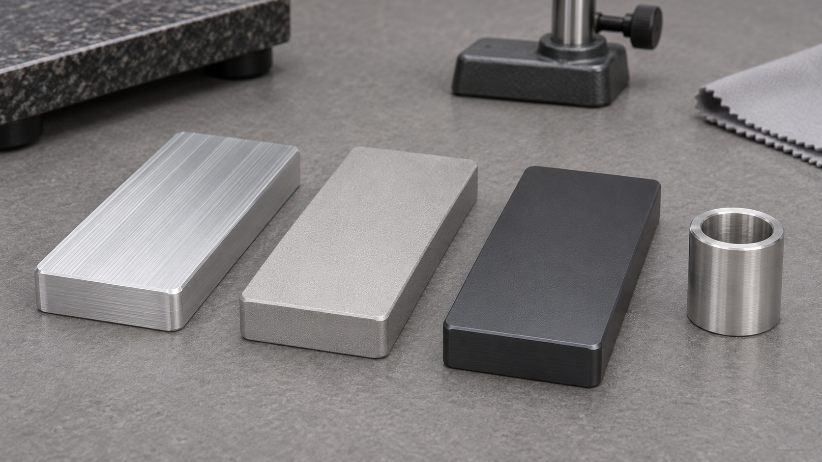
Even a prototype should be checked against the drawing. Identify the characteristics that control fit and function, agree how they will be measured, and request results before the part is used in assembly. An independent technical drawing guide explains why a controlled drawing and model must agree.
Rapid prototyping CNC milling can hold tight tolerances, but only when the drawing says which features need them and the supplier plans accordingly. A measured first article gives confidence that the process is capable before more parts are made.

Frequently Asked Questions
How fast is rapid prototyping CNC milling? Simple parts can often be finished within a few days once the program and material are ready, though complex geometry or finishing adds time.
Is it better than 3D printing for prototypes? For functional parts in production materials, milling usually gives better strength and surface quality. Printing can be faster for highly complex shapes that will not carry load.
Can a prototype be scaled to production? Yes. Rapid prototyping CNC milling uses production-grade equipment, so a validated part can usually move to larger volumes with the same route.
How Rapid Prototyping CNC Milling Fits Product Development
Product development moves through stages, and each stage asks different questions of a prototype. An early concept model answers whether a shape is practical. A functional prototype answers whether a mechanism works. A near-production prototype answers whether the part can be made consistently. Rapid prototyping CNC milling can serve all three because it uses real material and production-grade equipment.
At the concept stage, speed matters most. A simple milled part can be produced quickly from a model, held in the hand, and reviewed with the team. Changes are absorbed by editing the program rather than rebuilding tooling, so several iterations are affordable.
At the functional stage, material and tolerance matter more. A milled prototype in the intended alloy can be tested under load, assembled with mating parts, and measured against the drawing. This is where rapid prototyping CNC milling shows its advantage over visual-only prototype methods.
Before production, the same route can produce a small batch for pilot assembly and process validation. The data from that batch informs the final drawing and helps confirm that the design is ready for a larger commitment.
Comparing Prototype Methods
Different prototype processes suit different needs. The table below summarizes where rapid prototyping CNC milling sits relative to other common routes.
| Method | Strength | Limitation | Best use |
|---|---|---|---|
| CNC milling | Real material, tight tolerance | Limited internal geometry | Functional prototypes |
| FDM printing | Low cost, fast | Layer lines, weaker | Concept models |
| SLA printing | Fine surface detail | Material limits | Visual models |
| Soft tooling | Production-like process | Tooling cost and time | Pre-production runs |
The right choice depends on what must be proven. If appearance is the only question, printing may be enough. If the part must carry load or mate precisely, rapid prototyping CNC milling is usually the better investment.
Planning the Machining Strategy
Before a machine runs, the supplier plans how the part will be held, which tools will be used, and in what order features will be cut. This strategy has a direct effect on accuracy and cost. A well-planned route finishes critical features in one setup wherever possible, reducing the chance of misalignment.
Tool selection balances speed against finish. A larger cutter removes material quickly but cannot reach fine corners; a smaller cutter reaches detail but takes longer. Choosing the right combination is part of the experience a good supplier brings to rapid prototyping CNC milling.
Fixturing deserves similar attention. A part held securely and repeatably can be machined accurately, while a part that moves under cutting force will show error. For small or irregular prototypes, a custom fixture may be worthwhile even for a single part.
Finishing and Appearance
As-milled parts show tool marks, but many prototypes do not need a cosmetic finish. When appearance matters, options include sanding, bead blasting, anodizing, plating, painting, or polishing. Each adds time and cost, and each may change dimensions slightly.
For anodized aluminum parts, color can vary between batches if process conditions differ. Our guide on anodized color variation explains the reasons. Planning the finish early avoids a surprise at the end of rapid prototyping CNC milling.
Edge condition is another detail worth specifying. Internal edges and lead-ins affect how a part assembles, and a general deburring note may not be enough. Mark where a defined chamfer or radius is required.
From a Single Prototype to a Repeatable Process
A useful prototype leads to a decision, and that decision often leads to more parts. When the design is approved, the program, setup, material, and inspection record should be kept together. This allows rapid prototyping CNC milling to repeat the same result without rediscovering the setup each time.
If a change is needed, issue a new revision and confirm how it affects the process. A feature that changes a datum or a critical tolerance may require a different approach. Recording the reason for the change helps later orders stay consistent.
Suppliers that manage both prototypes and production reduce friction at this stage. The same team that validated the design understands what made it work and can carry that knowledge forward.
Common Mistakes in Prototype Projects
One mistake is requesting a prototype in a material that will never be used in production, then drawing conclusions about performance. The test result may not transfer. If a substitute is unavoidable, document it and treat the result as indicative.
Another is leaving the drawing vague. A model alone may show geometry but not tolerance, material, or finish. A controlled drawing complements the model and tells the supplier which features matter.
A third is skipping inspection. A prototype that looks right can still be out of tolerance on a critical feature. Measuring it against the drawing before assembly prevents wasted time and misleading test results.
Understanding Cost in a Prototype Order
A prototype quote reflects more than the material removed. Programming, setup, fixturing, machining time, and inspection all contribute. For a single part, programming and setup make up a large share, which is why the first piece costs much more per unit than a later batch.
Design choices influence each of these. A part with fewer setups, standard tool sizes, and simple fixturing will be cheaper. A complex part with deep pockets, tight internal radii, and several tight tolerances needs more programming, slower cutting, and more inspection. None of these is wrong, but each should be chosen deliberately.
Material also affects cost. Aluminum cuts quickly and is usually economical, while stainless steel and titanium slow the process and wear tools faster. Engineering plastics can reduce cost where strength requirements allow. Discussing the material early helps balance performance against budget.
Inspection is worth keeping. A measured prototype confirms that the process delivered what the drawing asked for. Skipping it may save a small amount now but can lead to false conclusions during testing.
Working With a Milling Partner
The most useful supplier contributes before the first cut. A design review can identify a radius that is hard to machine, a tolerance that is tighter than needed, or a feature that would benefit from a different approach. These suggestions are most valuable while the design is still flexible.
Ask how the supplier handles changes. If a revision arrives mid-project, the drawing should be updated, the program adjusted, and the inspection criteria reviewed. A clear process prevents an old version from being machined by mistake.
Communication should be structured. Route technical questions through one contact, answer them in writing, and share clarifications with everyone involved. Rapid prototyping CNC milling projects often move quickly, and a short written record keeps that speed from turning into confusion.
Applications Across Industries
Aerospace teams use milled prototypes for structural brackets and lightweight components that must be tested under realistic loads. Automotive developers use them for trial parts and sensor brackets before committing to production tooling. Medical device projects need precise components in materials that can be cleaned and inspected.
Industrial equipment relies on custom parts, fixtures, and transmission components where fit matters. Consumer electronics uses milled prototypes for housings and functional parts during trial sales. Research teams use them for lab fixtures and test articles where geometry is unique.
The common thread is that each application needs a real part, not just a visual model. Rapid prototyping CNC milling delivers that part with the material and accuracy needed to answer the question at hand.
Preparing a Request for Quotation
A complete request includes the model, a controlled drawing, the material and condition, the quantity, the critical features, the finish, and the inspection requirement. State the delivery date and whether the design may still change. If a first-article report is needed, say so at the request stage.
Ask each bidder to explain the proposed setup and flag assumptions. An alternative material or a relaxed tolerance is a proposal to review, not an approved change. Keeping the comparison on the same scope makes the price meaningful.
For teams new to working with an overseas supplier, our RFQ checklist sets out how to compare offers fairly.
Final Thoughts
Rapid prototyping CNC milling gives teams a practical way to validate a design before committing to production. It uses real material, holds tight tolerances, and can scale into larger volumes when the design is approved.
The best results come from a clear drawing, a sensible material choice, and an agreed inspection scope. With those in place, a prototype becomes reliable evidence rather than a best guess.
Conclusion
Rapid prototyping CNC milling is most effective when the prototype is treated as evidence. Define what the part must prove, choose a material that supports that test, and measure the features that matter. A well-planned prototype answers design questions early and gives production a reliable starting point.
Whether the next step is a design change, a small batch, or full production, the same discipline applies: keep the drawing, material, process, and inspection record together. That continuity is what makes rapid prototyping CNC milling a dependable part of product development rather than a one-off service.
As a final check, confirm the drawing revision, material grade, tolerance, finish, and inspection scope before releasing the order. Rapid prototyping CNC milling rewards a clear request, and a short review protects both the schedule and the result.
One last consideration is timing. Rapid prototyping CNC milling is fast, but rushing the drawing review often costs more time than it saves. A few careful decisions at the start keep the prototype useful and reduce the chance that it must be remade.