
Cross drilled holes can look clean at the entrance while a fragment remains where the passage meets another bore. In CNC machining, a diameter check at the mouth can miss that edge. If the passage carries fluid, or sits beside a moving component, an overlooked burr may create an obstruction or become loose during use. The important question is what remains at the intersection after the final operation.
To inspect cross drilled holes reliably, start by locating the affected edge on the drawing and model. Then agree how it will be reached, what material may be removed, and what evidence will show that the result is acceptable. A note that simply says “deburr all edges” gives little direction when the edge is hidden and a nearby bore must retain its function.
Cross Drilled Holes: First Distinguish a Burr from a Loose Chip
Before choosing a correction for cross drilled holes, inspect a representative part. Is the feature attached to the intersection, folded against the bore wall, or free to move? Note which operation produced it and whether subsequent machining changed its position. Cleaning can remove loose swarf, but flushing alone is not evidence that an attached edge projection has been removed.
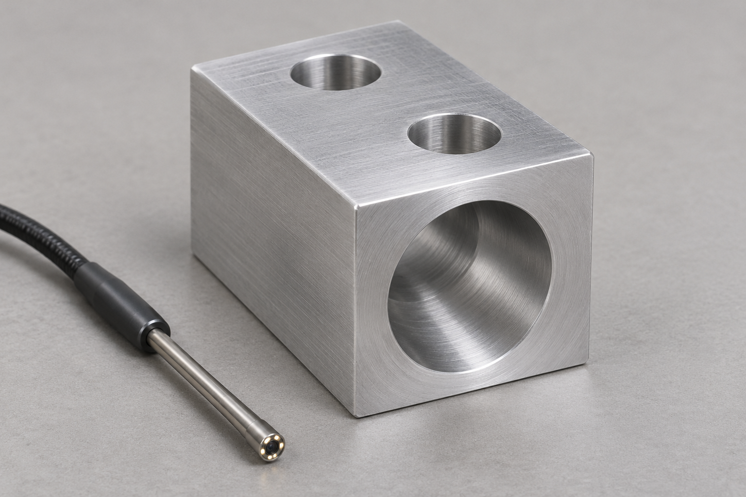
Keep the inspected location identifiable. A photograph of a clean hole entrance does not establish the condition of the whole crossing. Where direct viewing is impractical, review whether a suitable borescope can actually see the relevant edge. For first-article development, a sacrificial section may provide additional evidence if its preparation and interpretation are agreed. It cannot be used as the inspection method for every delivered component.
Cross Drilled Holes: Reduce Burr Formation Before Choosing a Removal Tool
For cross drilled holes, published guidance on drilling sequences is useful. Sandvik Coromant’s cross-hole guidance, within its discussion of indexable insert drilling, identifies chip evacuation and difficult deburring at the crossing as specific concerns. For different hole diameters, it recommends drilling the larger hole first to reduce burr formation. Its feed guidance applies to the drill type and application described; it is not a universal instruction to reduce every drilling feed by the same amount.
Review the proposed sequence with the tool supplier against the actual material, bore sizes, intersection angle and tool access. Check that a change intended to reduce the burr does not create another problem with tool stability or chip removal. Retain the final inspection requirement even when the revised sequence produces a visibly smaller burr.
Published work by Ohshima, Maekawa and Murata also found that cross-hole burr formation depended on factors including diameter difference and feed near breakthrough in the materials studied. Those experiments support checking the specific application. Their results do not establish a deburring success rate for a different alloy, tool or component.
Why the Intersection Geometry of Cross Drilled Holes Changes the Approach
The reason cross drilled holes are difficult is not the diameter of either bore; it is the shape created where two passages meet. A straight through-hole presents a predictable entry and exit, so a chamfering tool can follow a known path. An intersection produces a curved, partially hidden edge that changes shape as the two diameters and the angle between them change. A tool that works at a ninety-degree crossing of equal holes may not reach the same edge where a small bore enters a large one at a shallow angle.
This is why a review of cross drilled holes should start with geometry rather than with a catalogue of deburring tools. Record the diameter of each bore, the angle at which they meet, the direction from which a tool could approach, and which surfaces nearby must stay untouched. When several cross drilled holes join a common gallery, the order in which the passages were machined can also matter, because a later drill can push a burr from an earlier operation deeper into the network.
Where the geometry cannot be reached by a standard tool, the practical options are to change the machining sequence, design a dedicated tool path for that specific part, or revise the feature so the edge becomes accessible. Each option has a cost and a risk, and none should be assumed suitable without a trial on the actual material. The purpose of the geometry review is to narrow the choices before any cutting begins, not to promise that one method will work for every crossing.
How Material and Surface Condition Affect the Deburring Decision
The material of cross drilled holes influences both how a burr forms and how it can be removed. Ductile alloys tend to fold a continuous edge at the intersection, while harder or more brittle materials may fringe or micro-chip instead. A method that cleanly shears a burr in one alloy can smear material over the bore wall in another, especially when the cutting edge is dull or the speed and feed are wrong for that grade.
Surface condition matters as well. Cross drilled holes in a part that will later be plated, anodised or coated need the edge prepared before finishing, because a coating can cover a burr without removing it and can change the effective diameter of a tight bore. If the passages will carry fluid, the cleaning method must be compatible with the deburring method so that removed fragments are carried out rather than driven further into the network.
For cross drilled holes in cast or near-net-shape components, the starting condition of the passage can vary from one casting to the next, even within the same batch. That variation is a reason to confirm the method on several samples rather than a single part. Heat treatment and hard finishing can also change the material response after the hole is drilled, so the sequence of operations should be reviewed as a whole. None of these observations removes the need to qualify the chosen method on the actual component and material condition.
In-Process Controls Versus Final Inspection for Cross Drilled Holes
Burr control is easier to manage during machining than to repair afterwards. For cross drilled holes, in-process controls include keeping drills sharp, confirming the drilling order, watching chip evacuation, and stopping to inspect the first article before the rest of the batch is cut. These checks do not replace final inspection, but they reduce the chance that a difficult edge is produced in every part and then has to be found and corrected one by one.
Final inspection of cross drilled holes answers a different question: does the delivered part meet the agreed requirement? That inspection should be defined independently of the machining process, with its own acceptance criteria and record. A process check may say that the deburring tool was used; a final check must say what was found at the edge. Confusing the two is a common cause of disputes, because a completed operation is not the same as a verified result.
The two layers work best together. When in-process signals show that the burr is growing or changing, the process can be adjusted before more parts are made. When final inspection repeatedly finds the same edge condition, the machining sequence or tool can be reviewed rather than treating each part as an isolated rework. For cross drilled holes that are hard to view directly, agree in advance which sampling level and which viewing method will represent the batch, and record the limits of that method honestly.
Common Specification Mistakes to Avoid
The most frequent problem in a drawing requirement for cross drilled holes is vagueness. Phrases such as “deburr to visual satisfaction” or “remove all burrs” leave the operator to decide both the method and the limit, which produces inconsistent results and no clear basis for acceptance. A usable requirement states which edges matter, how much edge break is permitted, and which adjacent features must be protected.
A second mistake is setting a numerical burr limit that cannot be measured at the location in question. If the edge of cross drilled holes sits inside a crossing that cannot be viewed or gauged, a stated height in millimetres may be impossible to verify on the finished part. In that case, a functional criterion, a first-article section agreed with the customer, or a defined process + inspection combination is more honest than a number that appears precise but cannot be checked.
A third mistake is treating cleanliness and edge condition as the same requirement. A passage can pass a flush test and still hold an attached edge, or show a clean edge at the entrance while a detached chip remains deeper inside. Cross drilled holes used for fluid, lubrication or air should have the cleaning and the edge requirements written separately, with the inspection evidence for each. Clear separation avoids the false confidence that comes from passing one test and assuming the other has also passed.
Questions to Ask Before Approving a Deburring Method
Before accepting a proposed method for cross drilled holes, ask what evidence supports it on this material and this geometry. A method name is not a result. Request a sample trial, the settings that were used, and the inspection findings from that trial. Ask how the method reaches the specific intersection, what it may remove from nearby surfaces, and how it handles more than one crossing in the same part.
It is also reasonable to ask what the method does not do. For cross drilled holes with several branches, a process may clean the intersections it can reach and leave others untouched. Understanding that boundary before approval is better than discovering it after production. Ask how removed fragments are cleared, whether any secondary cleaning is required, and what checks will confirm that the result is repeatable across a batch.
Finally, agree who owns the acceptance decision. For cross drilled holes on a safety-relevant or function-critical part, the supplier should not silently redefine the requirement to match whatever a chosen tool can achieve. If the agreed edge cannot be reached, the correct outcome is a documented discussion about geometry, access or design change, not a quiet reduction of the standard. These questions are a checklist for conversation, not a guarantee of any particular outcome.
Documenting the Standard for Repeat Production
Once a method and an inspection approach are agreed for cross drilled holes, record them in a way that a later shift or a different supplier can follow. The record should capture the bore sizes, the drilling order, the removal method and its key settings, the permitted edge break, the protected surfaces, the cleaning step and the inspection evidence. A short, precise record is more useful than a long description that leaves the critical details implicit.
For repeat orders of cross drilled holes, the record also defines what should trigger a re-review. A change of material lot, tool supplier, drill geometry, heat-treatment condition or coating can alter how the burr forms and how the method behaves. Treating any of these as a controlled change, rather than a routine substitution, prevents a small input change from silently changing the edge condition at the intersection.
Good documentation also helps when a question arises after delivery. If the condition of cross drilled holes is ever disputed, a clear record of what was agreed and how it was inspected gives both sides the same reference point. YUEYI can review drawings and inspection expectations as part of a project discussion, but any burr limit, edge treatment or acceptance method must be agreed for the specific part and confirmed on samples before it is treated as a production requirement.
Match the removal route to the internal geometry
A tool that reaches the back of a straight through-hole may not follow the edge of an intersecting bore. HEULE describes dedicated, application-specific mechanical solutions for crossbores, including multiple crossbores entering a main bore. Treat that as evidence that geometry matters, rather than evidence that one stock tool will handle every intersection.
| Route to review | What must be established | Acceptance risk |
|---|---|---|
| Change drilling sequence or tool strategy | Tool supplier’s guidance for the material and crossing | A smaller burr may still remain attached |
| Purpose-designed mechanical deburring | Access, intersection geometry, cutting path and allowed edge removal | Uncontrolled cutting can alter a functional bore or edge |
| Specialist deburring process | Applicability to the alloy, passage network, surface condition and cleaning plan | A process must be qualified on the actual part; its name alone proves no result |
| Design change | Permission to change access, intersection location or local geometry | Improved access may conflict with sealing, flow or assembly requirements |
These are review options, not interchangeable repair instructions. Ask for an application trial before accepting a method that could change a controlled edge. If a specialist process is proposed, request its limits and required post-process checks instead of assuming that every concealed surface will be treated equally. No specialist deburring capability is claimed for YUEYI by this comparison.
Make the drawing requirement measurable
On the drawing, identify which cross drilled holes and internal intersections matter. Where an edge break is permitted, define its allowable extent and protect adjacent sealing lands, locating bores and other functional surfaces. If the engineering requirement is still undecided, resolve it during drawing review rather than leaving an operator to choose an arbitrary chamfer.
Separate the attached-edge requirement from the cleanliness requirement. An edge can be free of a visible projection while a detached chip remains elsewhere in the passage. Conversely, a clean flushing result does not establish the geometry of the internal edge. Set the inspection and cleaning evidence for the actual service conditions; there is no single particle limit or visual criterion that fits every machined component.
Mark the intersection and protected surfaces.
Agree access, method and permitted edge removal.
Inspect the edge and check cleanliness separately.
What to check before releasing the batch
Use the first article to confirm that the proposed inspection can find the defect you are trying to prevent. Record the bore and intersection identity, inspection stage, viewing method and acceptance criteria. If the view does not cover an edge, record that limitation and agree another way to address it.
After deburring, check any dimensions or surface features the operation could affect. Verify cleaning after the relevant final machining and finishing steps, and protect open passages during packing. Determine production sampling and any additional checks from the part’s risk and contractual requirements. A single successful assembly trial is not a substitute for an agreed inspection plan.
These steps keep cross drilled holes free of harmful burrs in a repeatable way; for quotation, provide the current model and drawing, material condition, passage function, critical intersections, permitted edge treatment and required inspection records. YUEYI can review these inputs with your CNC machining request. Use the RFQ checklist to keep the scope consistent, and distinguish edge acceptance from the dimensional controls discussed in our fit-and-function guide. Send the drawing for a project-specific review before committing to a removal method.
Technical references and scope
- Sandvik Coromant: Irregular surface drilling — cross-hole considerations within drill-specific guidance.
- HEULE: X-BORES — geometry-specific mechanical deburring applications, not a YUEYI equipment claim.
- Ohshima, Maekawa and Murata, Burr Formation and Deburring in Drilling Cross Holes (1993) — research context; its material-specific results are not transferred as production guarantees.
Cover: AI-generated illustrative visualization of a machined block and inspection probe. It is not a YUEYI production sample, inspection result or verified internal passage design.