
When thin wall distortion appears after unclamping, a thin aluminum housing measures correctly while it is held in the fixture, then rocks on the inspection surface after release. Taking another finishing pass may make the next measurement look better without solving the cause. First establish whether the part is changing under the clamps, during cutting, or after material removal.
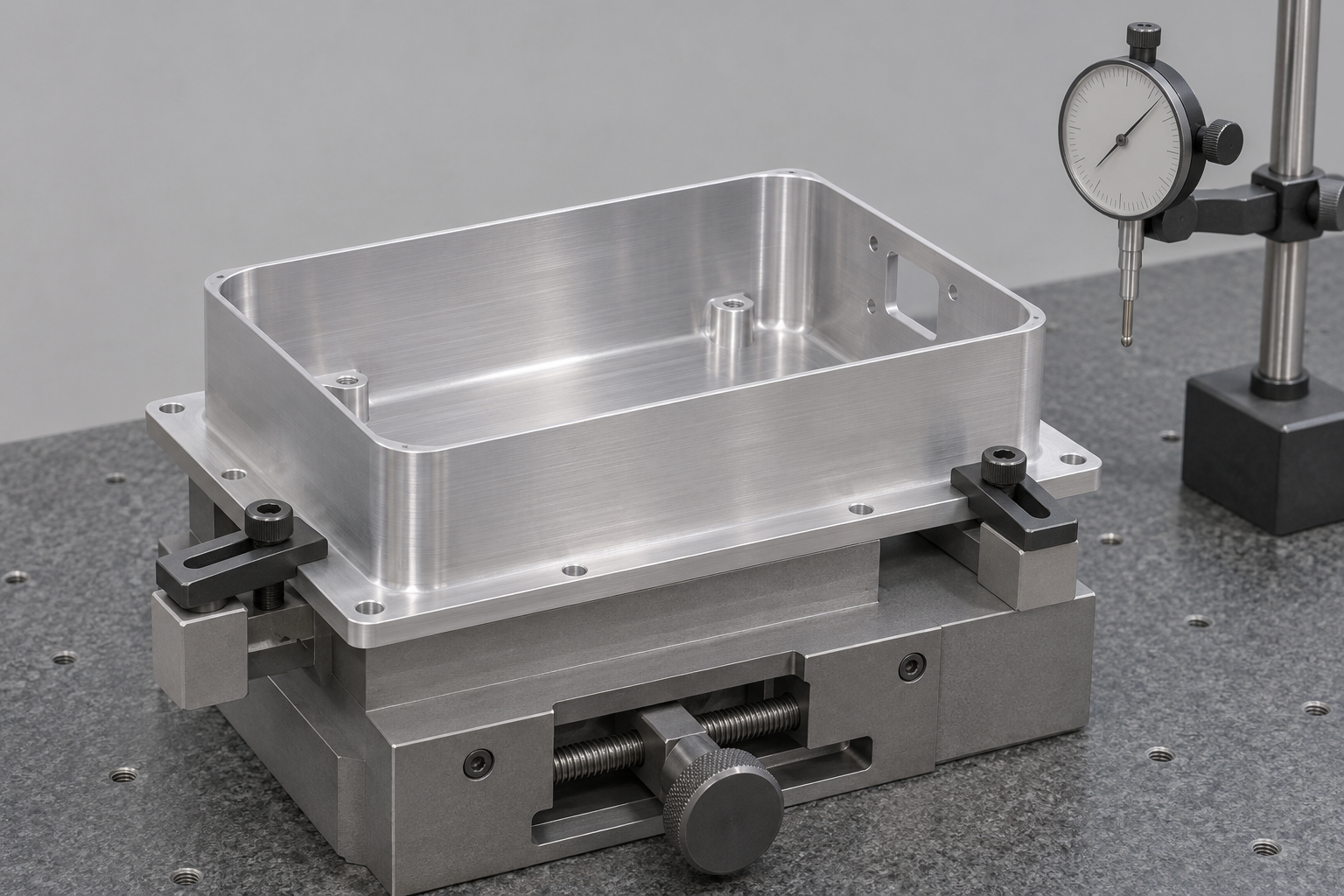
These mechanisms call for different changes. A fixture can temporarily flatten a flexible base; cutting loads can push a wall away from the tool; residual stresses can redistribute as stock is removed. A single measurement taken with the clamps tight does not distinguish them.
Thin wall distortion: fixture effect versus machining effect
Before changing the toolpath for thin wall distortion, compare the same features at defined stages: lightly located, securely clamped, immediately released, and ready for final inspection. Keep the support points and measurement procedure consistent. Record the clamping sequence and setting so another operator can repeat the comparison.
If a face moves when the clamps are applied before any cutting, investigate the fixture first. Check for chips under locators, unsupported spans, uneven contact and clamps acting far from backing supports. Carr Lane explains that work supports resist deflection; they perform a different job from clamps. A support must not be used to force an already distorted surface into an arbitrary position.
Compare located and clamped shape.
Compare clamped and released shape.
Verify using the agreed supports and datums.
Match the change to the observed behavior
| Observation | First review | What the change must preserve |
|---|---|---|
| Shape changes before the first cut | Locator contact, support location and clamping sequence | Secure restraint against machining loads |
| A wall varies with cutter position or shows chatter | Tool reach, engagement and local wall support | Reliable chip formation and safe clearance |
| Shape changes after substantial stock removal | Material condition and removal sequence | The drawing’s required alloy and temper |
| Inspection results depend on how the part is held | Inspection restraint and datum simulation | The specified functional acceptance condition |
This table is a troubleshooting aid, not a diagnosis from appearance alone. Several causes can occur in the same component.
Keep useful support until the finishing operation
Wall height, thickness and the remaining material influence thin wall distortion and the milling strategy. Sandvik Coromant’s thin-wall guidance describes staged removal and approaches that retain support below the cut. It also calls for attention to both cutter and wall stability. Apply those principles to the actual geometry rather than copying a depth of cut from an unrelated part.
For a housing with accessible outer faces, the programmer can assess whether alternating operations leaves a more stable section than finishing one unsupported wall early. For an enclosed pocket, access may prevent that route. Extra setups can improve support but introduce another reference transfer. Compare the complete route, including how the final holding features will be removed.
Reducing clamping force indiscriminately creates a different problem: the part may move during cutting. The aim is adequate restraint at suitable supported locations. Have the fixture designer check the loads and contact arrangement before testing a revised setting.
Do not use heat treatment as an unreviewed correction
Residual stress is one source of thin wall distortion and can originate in the stock and can also be introduced by machining. The SAE paper linked below documents both sources in aluminum components. That supports considering material condition and machining history; it does not establish a universal stress-relief cycle.
If a proposed remedy changes heat treatment or supply condition, obtain engineering approval and check its effect on the specified properties. A part that becomes flatter but no longer meets the material requirement is not an acceptable correction.
Define the state in which thin wall distortion must pass
Agree whether acceptance applies in the free state or under a defined restraint that represents assembly. Specify datums, support locations, critical faces and the measurement stage, including any later finishing. Record the temperature condition when it matters to the tolerance. Do not introduce an undocumented clamp just to make the inspection report pass.
If dimensions also change between the machine area and the inspection room, compare part and gauge temperatures before changing tool offsets. This is a separate check from movement caused by releasing a clamp.
For the drawing review, send the wall and base geometry, material condition, critical relationships and the intended assembly restraint. Our fit-and-function tolerance guide explains why size alone may miss the relationship that matters. To review a proposed CNC machining route, send YUEYI the current model and controlled drawing.
Why a clamped part can look perfect
Thin wall distortion starts with a simple fact: a flexible wall held flat by a clamp is not the same part as a free wall. While the fixture is closed, the clamps impose a shape that can mask the natural position of the material. The cutter then removes metal from a part that is being held in an artificial condition. When the clamps are released, the wall relaxes toward its stress-free shape and thin wall distortion becomes visible. The measurement did not change; the constraint did.
This is why thin wall distortion makes a first inspection taken in the fixture misleading. It proves that the part matches the drawing while restrained, not that it will match once free. For a thin-walled housing, the difference between clamped and free states can exceed the tolerance band. Deciding which state governs acceptance is a design question that must be answered before the process is tuned.
Understanding the mechanism avoids the wrong fix. Adding more clamps can make the in-fixture reading even better while increasing the stored energy released afterward. Reducing cutting load helps only if cutting force was the cause. Mapping the shape at each stage shows which factor dominates for a specific part.
How residual stress is released by cutting
Stock carries internal stress that can drive thin wall distortion from rolling, extrusion, casting or earlier heat treatment. As long as the section is thick, that stress can remain in equilibrium. Removing material upsets the balance, and the remaining thin section moves until a new equilibrium is reached. Thin wall distortion that appears progressively as more material is removed is a classic sign of this mechanism.
Machining can also introduce stress. Heavy cuts, dull tools and high cutting temperatures can work-harden or plastically deform a thin surface layer. The effect may be small per pass but accumulate across a pocket. A roughing strategy that leaves a consistent, modest stock allowance and allows the part to relax before finishing often reduces thin wall distortion compared with taking the wall to size in one aggressive pass.
Stress relief between operations can help, but it must be reviewed rather than assumed. A heat-treatment step changes material properties and dimensions, and it may affect other requirements on the drawing. Where residual stress is suspected, discuss the sequence with the material supplier and the design authority before adding a thermal step to control thin wall distortion.
Support strategy through the finishing cut
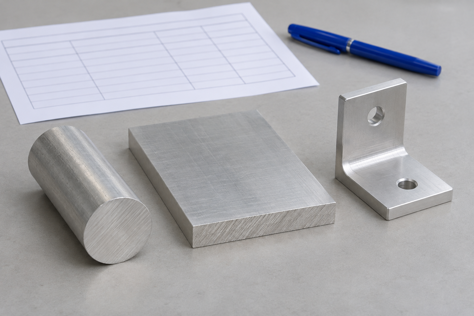
The goal of workholding for a thin wall is to support the part without imposing a shape that will spring back. That often means spreading support, using conformal or sacrificial fixtures, or leaving material in place until the last possible operation. Each choice trades access, cost and cycle time against the risk of thin wall distortion.
Sacrificial support or filler can stabilize a wall during cutting and be removed afterward. It is useful when the geometry allows it and when removal will not damage the finished surface. The decision should be documented as part of the process plan, including how the support is located and how the part is inspected once it is removed.
Sequence matters as much as the fixture. Leaving the base or a web until late in the route keeps the part stiff while other faces are machined. If a later operation removes that stiffness, expect the part to move again and plan a final verification after it. Thin wall distortion is best managed by controlling when the part becomes flexible, not by trying to clamp a fully flexible part flat.
Building a repeatable measurement record
Because the clamped and free states differ, a useful record states which one was measured. Note the support arrangement, the datum scheme, the location of the readings and the point in the process when they were taken. A number without that context cannot be compared with a later one, and thin wall distortion can be wrongly blamed on a process change that never happened.
Use the same supports in inspection that the drawing intends for function. If the part is assembled under restraint, agree a inspection fixture that represents that condition. If it must be free, support it so gravity and handling do not add their own deformation. The fit-and-function guide explains how to identify which features and states actually matter.
Repeat measurements after reloading the part. If the readings change with placement, the measurement setup is adding variation and should be corrected before the machining process is judged. Only once inspection is stable can it show whether thin wall distortion is being reduced by a process change. Preserve the early readings so the effect of each adjustment can be seen rather than guessed.
Choosing where to leave stock
A practical way to control thin wall distortion is to decide, feature by feature, where stock should remain until the last safe moment. A wall that will be thin in the finished part can be left thicker through roughing and reduced in a controlled finishing pass. A base that provides stiffness can be machined last so the part stays supported while other faces are cut. These choices belong in the process plan, not in a last-minute decision on the machine.
Leaving stock is not free. It changes cutting loads, tool engagement and the amount of material removed in the finishing pass, all of which can themselves introduce distortion. The aim is a balanced strategy in which each operation leaves enough material for the next one to hold the part and remove a consistent amount. A plan that removes almost everything in roughing and then takes a tiny finish cut can leave a stressed skin that moves when released.
Agree the stock strategy between the programmer and the fixture designer. They need to see the same sequence and the same definition of which surfaces are functional. If the drawing marks a face as a datum, that face may need to be created early and protected thereafter. Thinking through thin wall distortion at this stage is far cheaper than re-cutting a batch after it is complete.
Toolpath and cutting-load choices
Cutting force acts on a thin wall as a lateral load. A toolpath that pushes the wall away from the cutter can leave a spring-back error even if the program is dimensionally correct. Climb milling, stepdown, stepover and tool sharpness all influence the force, and the right combination depends on the wall geometry and the alloy. Published tooling guidance is a starting point; a representative part is the final check.
Constant engagement toolpaths can help by keeping the load steady rather than spiking at corners. Sharp tools with appropriate geometry reduce rubbing and heat, which matter when a wall is thin and has little mass to carry heat away. If a particular corner consistently shows thin wall distortion, look at how the tool enters and leaves that region before changing the overall strategy.
Measure the wall at more than one height. Distortion is rarely uniform, and a single reading at the top may miss movement lower down. Mapping the wall helps distinguish a clamping problem from a cutting-load problem: a shape that changes along the height often points to the tool path, while a uniform offset may point to the fixture. Recording that pattern turns thin wall distortion into a traceable effect.
Material condition and supply variation
Two blanks of the same alloy can behave differently if their temper or processing history differs. Stress from rolling or extrusion is not identical from lot to lot, and a change of supplier can change how much a thin wall moves. If thin wall distortion appears after a material change, review the condition and the stock form before adjusting the machining process.
Ask what condition the material is supplied in and whether a stress-relieved version is available. A change may help, but it needs engineering approval because it can affect strength, formability and cost. Treat it as a controlled material change with records, not an informal substitution made to solve a shop problem.
For repeat production, keep the material lot identified with the resulting inspection data. Over time that record shows whether thin wall distortion tracks a particular supply source. Without it, a material-driven effect can be misread as a fixture or program issue and corrected in the wrong place. Linking lot to outcome is a small discipline with a large payoff.
Deciding the acceptance state with the customer
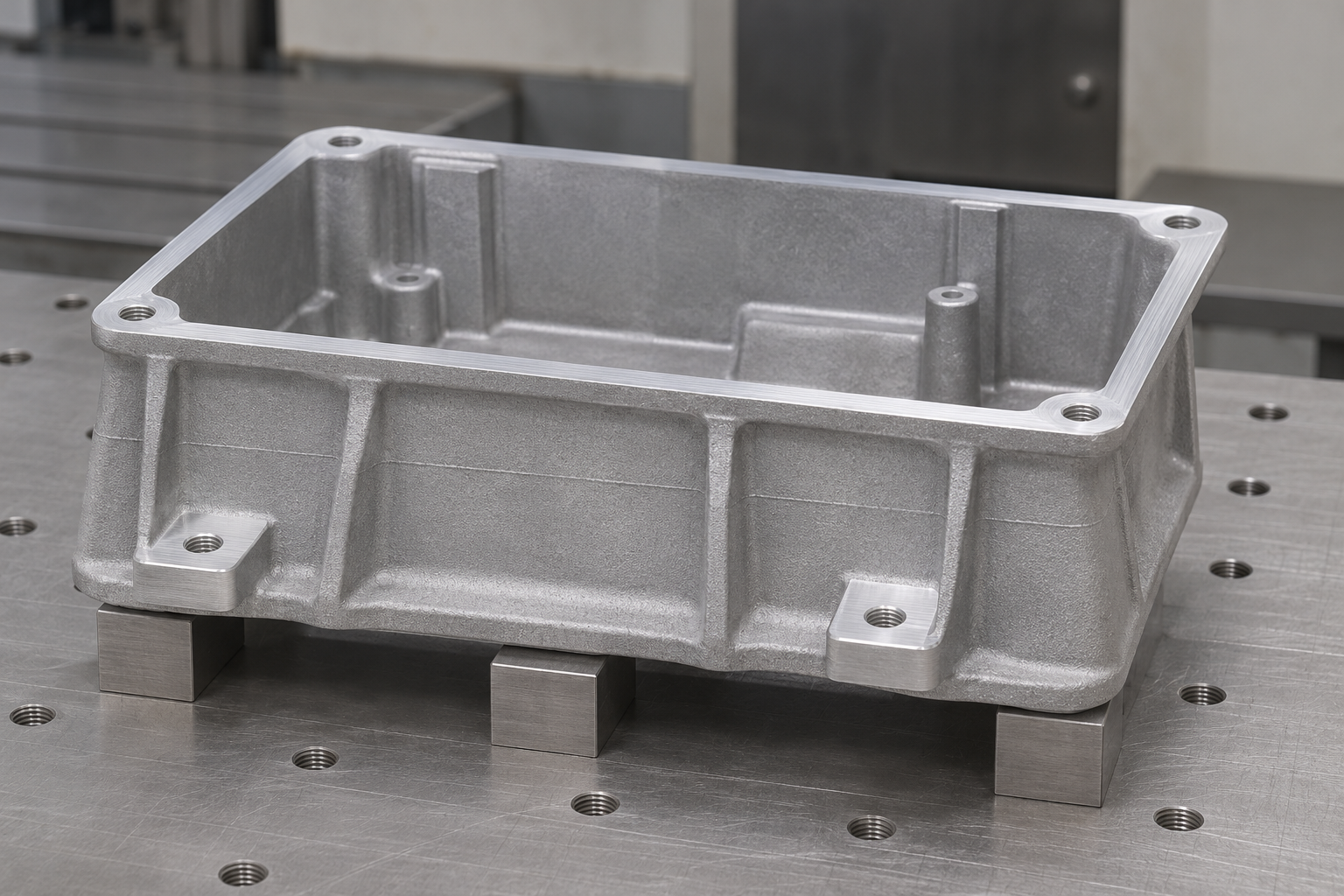
The drawing should say whether a thin-walled feature must meet its tolerance in the free state or under a defined restraint. A part that is bolted into an assembly may function correctly while constrained, even if it moves when free. Conversely, a part measured free but assembled under load may fail in service. Agreeing the acceptance state prevents thin wall distortion from becoming a dispute after delivery.
If restraint is required, define how it is applied in inspection: the support points, the torque or force, and the sequence. A loosely defined “as assembled” condition is not repeatable. If the part is accepted free, specify how it is supported so that its own weight does not deform it. Either way, the inspection method should be describable in a few sentences and reproducible by both parties.
Record the state on the inspection report alongside the result. A dimension reported without its restraint condition can be read two ways, and thin wall distortion makes that ambiguity consequential. Clear reporting protects both supplier and customer: the number means the same thing to everyone who reads it.

Recording the support points, the order of operations and the inspection state together gives the team a repeatable baseline. When a batch behaves differently, that baseline shows which variable changed instead of forcing a guess. Thin wall distortion is rarely caused by one factor alone, so a record that preserves each stage of the process is the most reliable route to a stable result.
Technical references
- Carr Lane: Hydraulic Work Supports — support function and workholding considerations.
- Sandvik Coromant: Shoulder Milling — thin deflecting walls and thin bases.
- Young, Nervi and Szabo: Machining-Induced Residual Stress and Distortion, SAE 2005-01-3317 — research context, not a YUEYI test result.
Cover: AI-generated illustrative visualization of an aluminum housing and workholding arrangement. It is not a delivered YUEYI part or measurement record.