
A machined housing can pass a bore diameter check and still fail assembly. The bore may be the correct size but sit in the wrong position relative to the mounting face. Tightening its diameter tolerance will not fix that problem. The drawing needs to control the relationship that makes the assembly work.
Start by marking the surfaces that locate the part in its assembly. Then identify the mating features and the variation each interface can tolerate. Those decisions should drive the CNC machining tolerances on the drawing. Otherwise, it is easy to spend inspection time on an outside dimension while leaving the actual alignment problem unresolved.

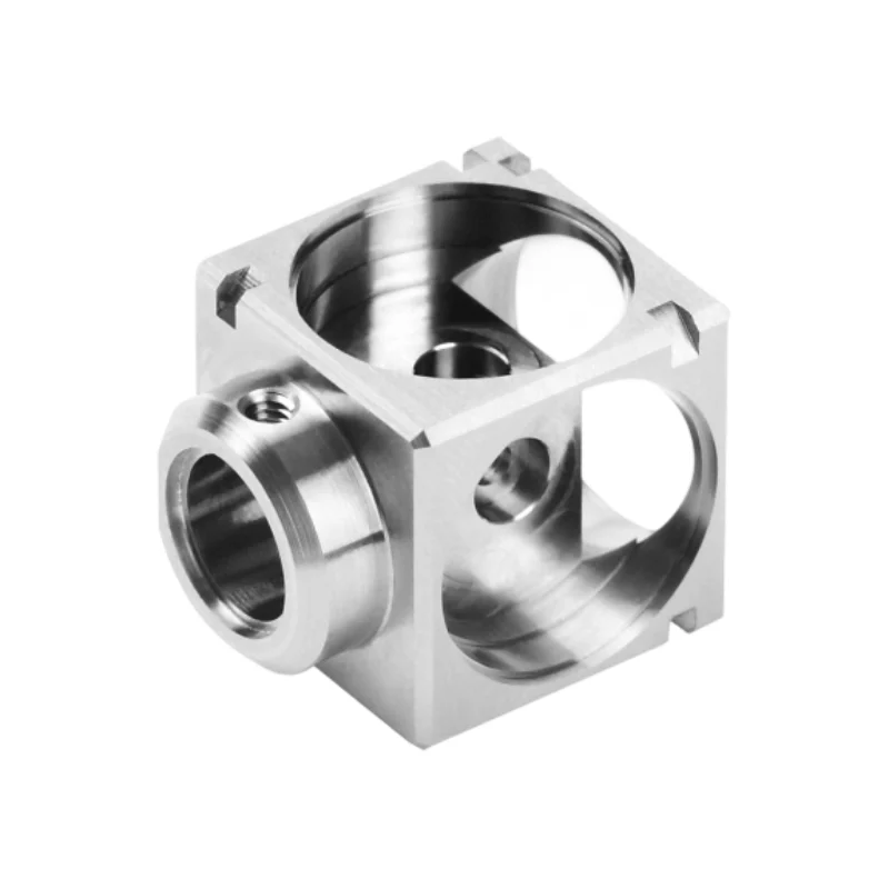
How to specify CNC machining tolerances from assembly requirements
Before assigning tolerances, identify the features that establish the part’s position in service. On a locating bracket, these might be a mounting face and two locating features. On a rotating component, they might be bearing seats and a shoulder.
Ask what happens if each feature changes. A clearance hole may tolerate variation without affecting assembly. A locating bore may influence alignment. A sealing face may require a specific surface condition. These features deserve different treatment because their consequences differ.
A useful drawing review records three things for every critical feature: its function, the variation that could cause failure, and how that variation will be checked. If the team cannot explain why a tolerance is needed, review it before releasing the drawing.
Bore diameter tolerance vs. position: what each controls
A size tolerance defines an acceptable dimensional range. Geometric controls address characteristics such as position, orientation, or form under the selected drawing standard. Surface texture describes another aspect of the surface. They answer different engineering questions.
| Functional question | Requirement to evaluate | Inspection planning question |
|---|---|---|
| Will a shaft enter a bore? | Mating sizes and the required fit | Which measurements or functional gauges establish acceptance? |
| Will two parts locate correctly? | Feature position relative to functional datums | How will the part be aligned during measurement? |
| Will a mounting face seat properly? | Relevant form and orientation controls | What support and measurement strategy represents the requirement? |
| Will a sealing interface perform? | Texture, geometry, material, and seal-specific requirements | Which characteristics need separate checks? |
The controls interact. Depending on the drawing standard and applicable rules, size requirements may also impose constraints on form. Do not assume that size, form, and location are entirely independent, or mix interpretation rules from different standards. ASME Y14.5 dimensioning and tolerancing provides a standardized language for these requirements. Identify the governing standard and edition on the drawing. [1]
Worked example: calculate clearance before choosing a fit
Consider an illustrative cylindrical shaft and bore, with all dimensions in millimeters and evaluated at the same reference condition. Assume the bore diameter is 20.000–20.021 mm and the shaft diameter is 19.980–19.993 mm. These are selected example limits, not a recommended fit or a YUEYICNC capability statement.
| Parameter | Example value | What it tells you |
|---|---|---|
| Bore diameter limits | 20.000–20.021 mm | Allowed bore size range |
| Shaft diameter limits | 19.980–19.993 mm | Allowed shaft size range |
| Minimum diametral clearance | 20.000 − 19.993 = 0.007 mm | Smallest clearance from the stated size limits |
| Maximum diametral clearance | 20.021 − 19.980 = 0.041 mm | Largest clearance from the stated size limits |
This calculation addresses diameter only. It does not demonstrate that the assembly will function: bore form, alignment, surface condition, temperature, and the mating components still matter. A positive diametral clearance cannot correct a locating bore positioned incorrectly relative to the assembly. Select the actual limits from the assembly requirements and applicable fit system, then agree how conformance will be measured.
For a worked thermal-expansion example and a record of the measurement conditions to compare, see temperature effects in aluminum part inspection.
Make the datum scheme reflect how the part is used
A datum establishes a theoretically exact reference used to interpret applicable geometric requirements. The physical feature on the component is the datum feature. In practice, its specification influences how inspection establishes the reference frame.
Consider an illustrative housing mounted against a base plate. If bore alignment matters relative to that mounting interface, the datum scheme should represent the functional relationship. Referencing a convenient outside surface that does not locate the housing in service can leave the intended relationship poorly controlled.
This is a design decision, not a universal instruction to choose the largest face. The appropriate scheme depends on assembly constraints, contact conditions, accessibility, and the governing standard. Discuss the proposed inspection alignment with the supplier before production when the relationship is critical.
Which CNC features actually need tighter tolerances?
A tight general tolerance can apply demanding limits to features that do not influence performance. It can also make the quotation harder to interpret: the supplier must determine whether every dimension truly requires that level of control.
Use an appropriate general requirement for ordinary features and call out exceptions where function justifies them. Review the general note’s scope, units, and standard edition. A general linear tolerance should not be treated as a complete specification for every geometric or surface requirement.
There is no universal tolerance that every CNC shop can guarantee on every component. Material, geometry, tool access, workholding, operation sequence, and inspection all affect feasibility. Request review against the actual drawing instead of relying on a machine brochure’s positioning specification.
Resolve deep bores and flexible features early
A deep bore is not simply a shallow bore with more cutting time. Tool reach and stiffness become more significant as the tool extends. Sandvik Coromant’s boring application guidance discusses tool overhang and stability, with different considerations for roughing and finishing. [2]
For a critical bore, discuss access, depth, finishing allowance, and the proposed process. Boring, reaming, or another finishing method may be appropriate, but the choice depends on the required geometry and material. A process name alone is not a guarantee of conformance.

Thin walls introduce a different question: what happens after the part is released from the fixture? A component held flat during machining or inspection can move when restraint is removed. Where the restraint condition matters to acceptance, specify and agree it rather than leaving each party to use a different setup.
Machining tolerances before and after surface finishing
Coatings and subsequent treatments can affect functional surfaces. If the component will be finished after machining, define the stage at which each critical requirement applies. Identify any masking or finishing restrictions that affect mating features.
For a locating bore, the useful question is whether the delivered bore must meet its requirement after all specified operations. A pre-finish inspection record does not establish the final condition unless the purchasing specification explicitly makes that the acceptance basis.
Avoid a blanket rule that every surface must receive the same treatment. A visible face, a bearing interface, and a threaded feature can require different handling.

Agree the inspection plan before cutting metal
For critical features, ask the supplier to confirm the measurement method, alignment, inspection stage, and report scope. A diameter reading does not establish bore position, and a list of coordinates is not automatically a valid assessment of the specified geometric control.
Temperature also deserves attention when dimensional limits are demanding. Renishaw’s guidance on CMM temperature compensation addresses workpiece temperature sensing and compensation. Check how those conditions will be handled when agreeing the measurement plan. [3] Instrument resolution alone does not establish the uncertainty of the completed measurement.
Before release, check that the drawing and CAD model share a revision, all critical features have an acceptance method, and conflicting requirements have been resolved in writing. The objective is a component that performs as intended, with evidence that both buyer and supplier can interpret consistently.
A bore can also meet its dimensional limits while an attached burr remains at an internal crossing. For those features, use the cross-drilled hole burr-control guide to define edge treatment and cleanliness checks separately from size and position.
What to send for a tolerance review
Prepare the current model and drawing, identify the mating component, and mark the features that control fit. Include the material, finishing requirements, and inspection evidence you need. A useful opening question for the supplier is: which requirements need clarification or a different manufacturing approach before this drawing can be quoted?
For a part review, explore YUEYICNC CNC machining services or send your drawing and project requirements.
References
[1] ASME — Dimensioning and Tolerancing, Y14.5
[2] Sandvik Coromant — Boring application guidance
[3] Renishaw — Temperature compensation
Why CNC machining tolerances Begin at the Assembly
CNC machining tolerances should be derived from the way a part locates and functions in its assembly, not copied from a blanket note on an older drawing. Start with the mating component: which surfaces make contact, which bore carries a shaft, and which face seals against a gasket. That functional map shows where CNC machining tolerances genuinely control performance and where a general workshop value is sufficient.
A housing mounted to a base plate illustrates the point. Its outside dimensions may be generous because they never touch another part, while the position of a locating bore relative to the mounting face can decide whether the assembled unit aligns. Spending inspection effort on the outside profile does not correct a mislocated bore.
Write down the failure mode for each critical interface before assigning CNC machining tolerances. If a feature can drift without changing fit, sealing, or movement, it rarely needs a special callout. This habit also makes quotations easier to compare, because every supplier prices the same set of controlled characteristics and the same acceptance evidence.
CNC machining tolerances by Feature Type
| Feature | What to control | Typical inspection approach |
|---|---|---|
| Locating bore | Position relative to functional datums | CMM alignment to the agreed datum scheme |
| Bearing seat | Size, roundness, and shoulder squareness | Bore gauge plus runout check |
| Sealing face | Flatness and surface texture | Roughness and flatness measurement |
| Clearance hole | General size only | Caliper or go/no-go gauge |
| Threaded feature | Thread class and engagement depth | Thread gauge and depth check |
The table is a starting point, not a specification. CNC machining tolerances for a bearing seat differ from those for a clearance hole because the consequences of variation differ. Applying CNC machining tolerances uniformly across every feature raises cost without improving function, so list exceptions only where the assembly justifies them and keep the general note for everything else.
Surface condition belongs in the same discussion. A diameter reading does not describe waviness, and a position result does not describe roughness. When the drawing separates these requirements, the inspection plan can address each one with an instrument suited to that characteristic rather than forcing a single measurement to cover everything.
How CNC machining tolerances Affect Cost and Lead Time
Tighter CNC machining tolerances usually require more finishing passes, slower feeds, controlled environments, and additional inspection. A feature that can be milled in one setup at a general tolerance may need boring, reaming, or grinding when the band narrows. Each extra operation adds machine time and another handling step where variation can enter the process.
Suppliers price risk as well as time. If CNC machining tolerances are ambiguous, a careful shop will include contingency for rework or interpretation disputes. Clear datums, defined measurement conditions, and an agreed acceptance method remove that uncertainty and often reduce the quoted price more than a small relaxation of the limits would.
Prototypes and production parts deserve different treatment. A one-off sample can be measured extensively and adjusted by hand, while a production run needs a stable process with statistical control. Discuss the intended volume when requesting a quote so the proposed manufacturing route matches the real requirement instead of an assumed one.
CNC machining tolerances Across Different Materials
Material behavior changes how CNC machining tolerances are held. Aluminum expands more than steel with temperature, so a bore measured in a warm shop may differ from one measured at 20 degrees Celsius. Thin-wall aluminum housings can also move when released from a fixture. CNC machining tolerances for such parts should state the inspection conditions, not only the dimensional limits.
Stainless steels work-harden and retain stress, while engineering plastics creep under load and absorb moisture. A tolerance that is straightforward on a rigid steel block may be unrealistic on a slender polymer feature. Ask the supplier to review CNC machining tolerances against the actual grade, wall thickness, and geometry before the drawing is released for tooling.
Coatings and heat treatment change dimensions too. Define whether a critical requirement applies before or after finishing, and note any masking needed for mating features. A pre-finish inspection record does not establish the delivered condition unless the purchasing specification explicitly makes it the acceptance basis.
Documenting CNC machining tolerances in the RFQ
A useful request for quotation packages CNC machining tolerances together with the model and drawing revision, the mating part, the material and finish, and the inspection evidence required. Mark the features that control fit. Then ask which of the CNC machining tolerances need clarification before the drawing can be quoted, and record the answers in writing.
Include the governing drawing standard and edition. Geometric controls follow rules that depend on that standard, and mixing interpretation frameworks leads to disagreement at goods-in. State the units, the revision of the CAD model, and how conflicts between the model and the drawing will be resolved before production starts.
For buyers managing several suppliers, a short tolerance review sheet keeps answers comparable. Record the proposed measurement method, the datum alignment, the inspection stage, and the report scope for each critical feature. Our CNC machining RFQ checklist expands this into a repeatable format that is easy to attach to every enquiry.
CNC machining tolerances and Inspection Evidence
Agree the measurement plan before cutting metal. A list of coordinates is not automatically an assessment of a geometric control, and a diameter reading does not establish bore position. CNC machining tolerances should come with a defined method, alignment, and acceptance rule for every critical feature, so that both parties interpret the same result in the same way.
Instrument resolution alone does not establish measurement uncertainty. Temperature, probe strategy, fixturing, and part cleanliness all affect the result. When CNC machining tolerances are demanding, ask how the supplier will handle these conditions and what documented evidence will accompany the shipment rather than relying on a pass or fail statement alone.
First-article inspection, in-process checks, and statistical control serve different purposes. The first confirms the setup, the second catches drift, and the third demonstrates stability over a run. Decide which records you need at the quotation stage rather than after parts arrive and a discrepancy has already appeared.
Common Mistakes with CNC machining tolerances
One frequent error is setting CNC machining tolerances tighter than the assembly needs, then expecting the supplier to absorb the cost. Another is leaving the datum scheme undefined, so inspection aligns the part differently from the way it mounts. Both problems are avoidable during a short drawing review before any steel is cut.
A third mistake is treating CNC machining tolerances as a substitute for a surface finish or edge requirement. Burrs at internal crossings, sealing-face texture, and thread condition need their own callouts. Add them separately so the acceptance criteria are complete and no characteristic is left to informal interpretation.
Finally, avoid releasing a drawing whose model and PDF carry different revisions. Small discrepancies in hole locations or radii become expensive when tooling is already cut and parts are in production. A simple version check takes minutes and prevents a scrapped batch or a delayed assembly build.
Frequently Asked Questions
How tight should CNC machining tolerances be? As tight as the function requires and no tighter. Derive each value from the mating interface and the failure mode, then confirm the supplier can measure it reliably.
Do CNC machining tolerances include surface finish? No. Size and geometric controls differ from texture, so specify roughness separately wherever sealing, wear, or appearance depends on it.
Why do quotes rise when CNC machining tolerances tighten? Extra finishing operations, slower cycles, controlled measurement, and rework risk all add cost and extend the lead time of the order.
Should prototypes use production CNC machining tolerances? Often not. Discuss volume early and adjust the inspection approach to the run size so a one-off sample is not priced like a full batch.
Which standard governs CNC machining tolerances? Name the drawing standard and edition, such as ASME Y14.5 or the relevant ISO GPS standards, and keep it consistent across the whole drawing set.
Technical Resources
For deeper reading on CNC machining tolerances, see ASME Y14.5 dimensioning and tolerancing, the ISO geometrical product specification standards, and independent guidance on preparing a technical drawing for CNC machining. A clear drawing reduces interpretation disputes more effectively than any single tolerance value, and it gives the inspection team a stable reference. Teams planning low-volume work can also review our small batch CNC machining guide for how process choices change between sampling and production.
Reviewing CNC machining tolerances on a new drawing? Explore our CNC machining services or send Yueyi your model, drawing, and mating-part details for a project-specific feasibility review.