
By Jay Zhou | Yueyi
Wear ring clearance is set by finish-turning the installed impeller wear ring from the drawing’s functional datum when the pump design calls for machining after installation. Then check the ring outside diameter, the mating casing ring bore, and radial runout separately. The diameter difference tells you the diametral running clearance. Runout shows whether the finished ring runs true to the specified axis. This guide explains how to establish, measure and document wear ring clearance on a renewable impeller ring pair.
Why a ring can pass diameter inspection and still rub
In a centrifugal pump with a renewable impeller wear ring, the ring rotates inside a stationary casing ring. The gap limits internal leakage, as KSB’s pump engineering reference explains. If the rotating ring sits off-center, one side of the gap gets smaller even when both diameters meet the drawing. An uneven seat, debris under the ring, or locating the impeller from a nonfunctional outside surface can contribute to that error.
At the same mating section, subtract the rotating ring OD from the stationary ring ID. For example, 100.40 mm minus 100.00 mm gives 0.40 mm diametral clearance. If both surfaces are round and concentric, that gives a 0.20 mm radial gap per side. These numbers illustrate the calculation only; the specified wear ring clearance for a real pump comes from the pump drawing or OEM manual, which also gives the acceptance limits.
The practical lesson is that wear ring clearance is a system result, not a single diameter. Two rings can show the correct average gap and still run out of true, taper, or close down on one side after assembly. That is why the inspection plan should treat size, form, and position as separate checks rather than assuming a passing diameter guarantees a healthy running gap.
Choose the finishing setup around the running axis
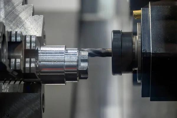
Check the impeller’s ring seat and shoulder before installation. Confirm the specified fit and retention method, and make sure the ring seats fully. If the ring is supplied with machining stock, install and retain it as specified before taking the finishing cut. Flowserve’s HED/HED-DS instructions, section 6.9.1, give a model-specific example of this approach for establishing wear ring clearance.
Mount the impeller from the drawing’s functional datum features, such as the mounting bore and seating face where specified. Indicate the setup before cutting. Check that clamping leaves the ring round after release and that there is enough stock to clean up the full circumference without turning below the size limit. If the seat cannot locate the ring reliably or the available stock will leave an undersize diameter, resolve the issue before machining.
| Machining route | When to use it | What to check |
|---|---|---|
| Install, then finish-turn the ring OD | The OEM specifies an oversize replacement ring for machining in place. | Ring seating, available stock, installed OD and runout to the drawing datum. |
| Install a ring already finished to size | The part specification explicitly allows a finished-size ring. | Fit, installed OD and runout after seating. Check wear ring clearance against the mating bore. |
Inspect size, runout and clearance separately
Measure the finished ring OD with a calibrated outside micrometer and the installed casing-ring ID with a suitable calibrated bore gauge or inside micrometer. Take readings at agreed angular orientations and axial sections along the running land. Compare paired sections and document the smallest evaluated diametral wear ring clearance. A few diameter readings can reveal taper or ovality, but they cannot establish the minimum assembled gap if the axes are offset.
For circular radial runout, reproduce the drawing datum setup. Place a suitable indicator on the running land and record the difference between the high and low readings through one full revolution at each specified section. Qualify the arbor or fixture so its own error does not dominate the reading. Follow the drawing and its governing standard if it calls for total runout. Record the measurement setup and results on the inspection report. Where the assembly procedure calls for balancing, follow the specified sequence after ring machining.
Wear Ring Clearance: Diametral Versus Radial Measurement
A recurring source of confusion is whether a stated wear ring clearance is diametral or radial. Diametral clearance is the difference between the casing bore diameter and the ring outside diameter. Radial clearance is the gap on one side, which is half the diametral value only when the two surfaces are perfectly round and concentric. Always read the drawing note or OEM manual to see which convention the limit uses before comparing a measurement to it.
When the axes are offset, the local gap is not half the diametral clearance at all. One side tightens while the opposite side opens, so the minimum local gap can be far smaller than the average. This is why runout and concentricity matter as much as the two diameters when assessing wear ring clearance. A report that records only average diameters can look acceptable while the running condition is not.
For documentation, state both the measured diameters and the calculated clearance, and name the convention used. If the specification gives a minimum and maximum diametral wear ring clearance, compare the paired section readings against that band and record the smallest evaluated value. Where a radial limit is specified, make the conversion explicit rather than leaving the reader to assume a factor of two.
Wear Ring Clearance: How Material and Temperature Affect the Reading
Metals expand and contract with temperature, and a wear ring clearance measured in a cool inspection room may differ from the running gap at operating temperature. If the rotating ring and the stationary casing ring are made from different alloys, their expansion rates differ, and the assembled clearance can grow or close as the pump warms up. The pump designer accounts for this, but the machinist and inspector should not treat a room-temperature measurement as the operating value without checking the drawing notes.
Both the measured part and the gauge should be at a stable, recorded temperature. Handling a ring for a long time can warm it enough to shift a tight tolerance, and measuring a casing bore soon after a hot process can give a misleading wear ring clearance. Where the specification calls for a reference temperature, such as 20 °C, bring the parts and gauges to that condition and state the correction method if a different temperature must be used.
Surface finish also interacts with the running gap. A ring finished too smoothly may not retain lubricant, while a rough land can wear the mating ring and change wear ring clearance over time. Follow the surface finish callout on the drawing, and record how it was verified. Any statement about expected service life should be tied to the pump’s operating conditions rather than assumed from a single measurement.
Wear Ring Clearance: Common Machining and Inspection Mistakes
The first mistake is finishing the ring to a nominal OD without checking the actual mating bore. Wear ring clearance depends on the pair, so a ring that is correct on paper can produce too tight or too loose a gap against a bore that has worn or been reworked. Measure the installed casing bore and use its verified size when deciding the finishing target, within the limits the drawing allows.
The second mistake is locating from a nonfunctional surface. If the impeller is mounted for machining on a corroded or damaged outside diameter rather than the specified datum, the finished ring can run out of true even though its diameter is correct. Reproduce the functional datum setup for both machining and inspection, and confirm that the fixture error is small relative to the runout tolerance.
The third mistake is treating one angular position as representative. Ovality and taper are common on worn casings and on rings that were clamped unevenly. Take readings at several orientations and axial sections, then report the evaluated wear ring clearance rather than a single convenient number. If a minimum assembled gap is critical, discuss with the pump designer how that minimum will be established before accepting a diameter-only inspection plan.

Wear Ring Clearance: When to Rework Versus Replace
A worn ring pair can sometimes be restored and sometimes cannot. If the casing bore remains within its allowable size and form, a new or re-finished impeller ring may restore the specified wear ring clearance. If the bore is oversize, out of round, or damaged, fitting a new ring alone will not recover the intended gap, and the casing may need repair or replacement. The decision should be based on measured condition, not on the assumption that a replacement ring fixes every case.
Rework is also limited by available stock. An oversize renewable ring is supplied with material to be finish-turned in place, but only up to a point. If the seat is uneven or the required cut would take the ring below its minimum diameter, the correct action is to stop and agree a different approach. Documenting the as-found condition before cutting helps support that decision and avoids removing material that cannot be replaced.
For critical pumps, agree the acceptance criteria with the owner or OEM before work begins. A repair that restores wear ring clearance to the drawing is different from a running clearance chosen by the shop to suit perceived conditions. Keeping that distinction clear protects both the equipment and the party doing the work, and it makes the inspection record meaningful when the pump later returns to service.
Wear Ring Clearance: Recording and Reporting the Result
A useful inspection record for wear ring clearance states the part and ring identification, the drawing revision, the instruments used and their calibration status, the measurement temperature, the datum setup, the individual diameter readings, the calculated diametral clearance, and the runout result. It should also name whether the clearance convention is diametral or radial. This level of detail lets a reviewer reproduce the result rather than take it on trust.
Where a reading falls outside the specified band, report the actual value instead of rounding it into acceptance. Note which section or orientation produced the extreme value and whether the condition suggests ovality, taper, or an offset axis. Any decision to accept, rework, or reject should reference the governing drawing and be recorded with the wear ring clearance figures that supported it.
Yueyi can review drawings and inspection expectations as part of a project discussion, but any stated wear ring clearance, edge treatment, or acceptance method must be agreed for the specific pump and confirmed on the actual parts before it is treated as a production requirement. The values in this guide are illustrative and do not replace the OEM manual or the revision-controlled drawing for the pump in question.

Wear Ring Clearance and the Role of Assembly Practice
Even a correctly machined ring pair can be compromised during assembly. The wear ring clearance established on the bench assumes the impeller is seated squarely and retained as designed. If debris is trapped under the ring seat, if the retaining feature is damaged, or if the impeller is drawn down unevenly, the finished ring can tilt slightly. That small tilt changes the local running gap and can produce a rub that the diameter inspection never predicted.
Before assembly, clean the ring seat and mating faces and inspect them for burrs or crescent marks from earlier removals. A raised edge on the seat can lift the ring at one point, so the measured clearance after tightening will differ from the free-state value. Confirm that the retention method is the one specified on the drawing, and that any locking feature is fitted in the orientation the design intends. Where a ring is supplied oversize for in-place finishing, do not assume the stock is uniform around the circumference; indicate the installed ring before the final cut.
After assembly, recheck the runout on the installed impeller using the same datum the machining setup used. If the reading has changed significantly from the free-state measurement, look for a seating problem before adjusting the ring diameter. Chasing a seating fault by removing more material from the ring can produce an oversize gap and still leave the underlying tilt in place. The correct sequence is to establish a sound assembly first, then confirm the running clearance.
Lubrication during initial rotation also deserves attention. A dry start can score the ring land and permanently change the surface that the clearance was measured against. Follow the pump manufacturer’s guidance for initial start-up, and record any observations from the first run. These assembly practices do not replace the dimensional checks described above, but they explain why a measured wear ring clearance and an actual running condition can diverge when handling is uncontrolled.
What to send for a quotation
Send the revision-controlled impeller and ring drawings, the STEP model if available, the casing-ring drawing or verified bore measurements with the measurement condition, and the OEM clearance limits. Include ring and impeller materials, fit and retention details, datum and runout requirements, surface finish, and quantity. For repair work, identify the pump model and share the condition of the ring seat. State whether the scope includes supply, installation, finish turning, dimensional inspection, or balancing, and identify the wear ring clearance acceptance band you expect to be held. See Yueyi’s turning and mill-turn services or send the drawings for review.
Frequently asked questions
Is diametral clearance the same as the gap on one side?
For round, concentric surfaces, the gap on one side is half the diametral wear ring clearance. With an offset, the local gap varies around the circumference and cannot be inferred from the diameter difference alone.
Can we use the old ring as the machining target?
Use the approved drawing or pump manual for the target. A worn ring can help diagnose where contact occurred and how the ring was retained, but it should not define the new wear ring clearance.
Does a balance report verify wear-ring runout?
A balance report records residual unbalance. Check runout against the specified datum and document it on the dimensional report; neither result substitutes for the other when assessing wear ring clearance.
Does this apply to an open impeller’s vane-tip clearance?
This guide covers a cylindrical ring pair and the wear ring clearance between them. Vane-tip clearance uses the geometry and adjustment procedure specified for that pump and is outside the scope of this article.
The figures and examples throughout this article are presented to explain inspection method, not to define acceptance for any specific pump. Real limits depend on the pump design, the ring materials, the operating duty and the revision of the governing drawing. Treat the OEM documentation as authoritative, and resolve any conflict between a general guide and the pump manual in favour of the manual. Where a duty is unusual, a short discussion with the pump designer before machining is more reliable than applying a generic rule to a part that will see demanding service.
Drawing reference ASME Y14.5, Dimensioning and Tolerancing. Apply the governing standard and revision specified on the drawing.