
A supplier checks a machined surface and records a passing surface roughness result. After finishing, the customer measures it again and rejects the part. Both readings may be genuine: they may describe different surface conditions, different locations, or different measurement settings. This article explains how to define the check so that the two parties are measuring the same requirement.
Check surface roughness at the stage that the requirement actually controls. A substrate requirement needs a measurement before the process that covers or changes that substrate. A requirement for the working surface needs verification in its specified final condition. When both matter, define two inspection stages instead of asking one result to prove both.
This is an inspection-planning approach, not a replacement for the drawing or its referenced standard. If the drawing leaves the stage unclear, resolve it with the design authority before production. A clear surface roughness instruction removes the ambiguity that turns a good part into a dispute.
Start with the surface’s job
A sealing face, a bonding surface, and a decorative cover have different acceptance needs. For a seal, the surface that contacts the seal matters. For a coating or adhesive process, the prepared substrate may need its own texture control. For a decorative cover, an average surface roughness value cannot fully describe visible streaks, scratches, or color differences.
Do not assume that a finer texture is always better. The design may depend on lubricant retention, controlled contact, or a defined preparation condition. The appropriate requirement follows the application, not the smoothest finish a supplier can produce. A lower surface roughness number is not automatically a better part if it defeats the function.
| What needs to be controlled? | Inspection stage to define | What that result does not prove |
|---|---|---|
| Machined substrate before a coating | After the agreed preparation, before it is covered | The roughness or integrity of the final coating |
| Finished functional surface | After the last specified operation affecting that surface | The condition of a substrate now hidden underneath |
| Masked functional area beside a treated area | After processing and mask removal, using the agreed method | Coating thickness or adhesion on the neighboring area |
| Visible cosmetic finish | In the final appearance condition | Visual conformity from a roughness number alone |
Map the route before choosing the checkpoints
Write the actual route beside the drawing: machining, deburring, preparation, finishing, cleaning, and any later corrective operation. The order varies with the part. Mark the last operation that can change each controlled surface, and define the surface roughness check immediately after it.
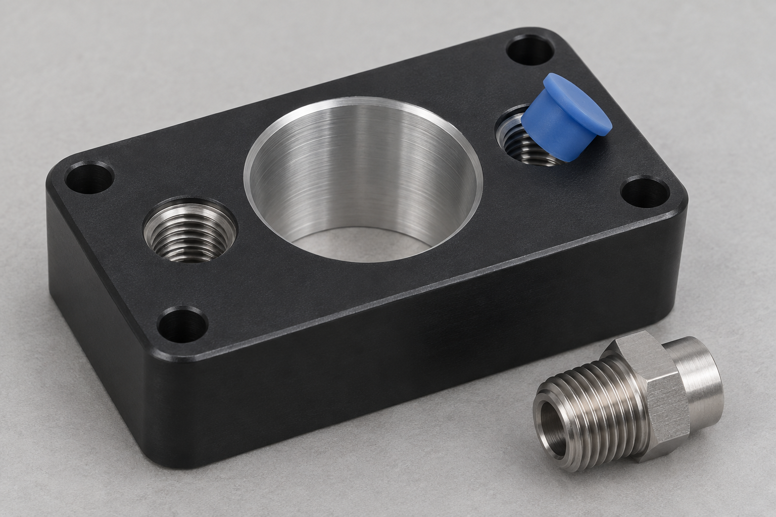
For an illustrative coated bracket, the bonding face might require a preparation check before coating, while a masked locating face needs final inspection after mask removal. These are separate surfaces and separate decisions. Neither should be inferred from a convenient reading on the large exterior face.
If the final condition fails, do not immediately polish the part until the number passes. Additional work may affect dimensions, edge geometry, or the finish itself. Review the proposed rework and repeat the affected surface roughness checks. The same coordination is needed when threads and anodizing share a dimensional acceptance requirement.
Make the measurements comparable
Before blaming the finishing process, compare the inspection instructions. A report containing only “Ra passed” is difficult to reproduce. Instrument method, filtering, trace direction, and sampling location can all change the reported surface roughness result.
- Identify the surface: use a drawing feature or marked inspection location, including the trace direction relative to the dominant machining pattern.
- Identify the parameter and units: do not interchange a profile parameter with an areal parameter or assume similarly named parameters use identical definitions under different standards.
- Record the measurement conditions: include the applicable standard and edition, instrument method, filtering and evaluation settings, and relevant probe details.
- Control the condition: specify the cleaning and handling procedure so contamination is not mistaken for surface texture. Check method suitability for a delicate or coated surface.
- Agree the sampling plan: define locations and quantities according to the feature and risk. One convenient trace is not automatically representative of the whole surface.
A contact stylus and an optical instrument do not necessarily produce interchangeable surface roughness results. Neither method is universally superior. Access, surface reflectivity, feature slopes, and the risk of touching a delicate surface can influence the choice. If customer and supplier use different methods, agree how correlation will be assessed before using the results for acceptance.
Choose the right parameter for the function
Ra is the most quoted parameter, but it is not the only one, and it is not always the most relevant. Ra averages the profile over the evaluation length, so two surfaces with the same Ra can have quite different peaks and valleys. A sealing surface may depend more on the height and spacing of peaks than on the average. A bearing or sliding surface may need a parameter that describes the valley structure that retains lubricant.
Profile parameters describe a two-dimensional trace; areal parameters describe a three-dimensional surface patch. They are not interchangeable, and similarly named parameters may be defined differently under different standards. When a drawing calls out a surface roughness value, it should also identify the parameter, the standard and edition, and any filtering so that the number has a fixed meaning.
For a critical surface, ask what physical behavior the value is meant to protect. If the answer is “we have always specified Ra,” the requirement may not be controlling the property that actually matters. A short discussion with the designer can replace a guess with a requirement that both supplier and customer can measure consistently.

Separate texture from isolated defects and appearance
Ra summarizes a profile; it does not describe every defect on a part. A localized scratch may be missed by the selected trace. A surface can also meet a surface roughness limit while having an unacceptable visible pattern. Treating the number as a complete description of the surface is a common source of rejection disputes.
Keep separate requirements for burrs, scratches, dents, coating defects, and cosmetic zones where those matter. Use an agreed appearance acceptance plan rather than trying to turn one roughness number into a complete visual specification. Where defects affect sealing or wear, the designer may need additional texture or functional criteria beyond the standard average value.
Resolve a before-and-after disagreement in order
- Preserve the evidence. Keep the part identification, process-stage records, measurement traces, settings, and photographs before rework.
- Check the requirement. Confirm which surface, processing stage, standard, and acceptance rule the drawing controls for surface roughness.
- Repeat under aligned conditions. Compare the same agreed locations and direction using suitable, verified equipment. Investigate unstable readings rather than averaging away a mismatch.
- Locate the change. Where intermediate records exist, compare them with final results. Without those records, do not claim the finish caused the problem solely because it was the last operation.
- Agree disposition. Decide whether the part needs rework, further evaluation, or a clarified requirement. A concession requires authorization; it is not a passing inspection result.
Work through these steps in order. Skipping to rework before the requirement and the conditions are understood destroys the evidence that would have explained the difference. A short pause to align the method usually resolves more than an immediate repeat measurement.
How machining marks shape the measurement
The way a surface is produced leaves a characteristic texture, and that texture affects the surface roughness reading. A turning operation leaves regular circumferential grooves; a milling operation leaves a directional pattern from the cutter; grinding, honing, and polishing each leave their own structure. Because a stylus trace follows a line across that structure, the direction of the trace relative to the machining marks changes the result.
For this reason, the inspection instruction should state the trace direction. Measuring across the lay of a turned surface gives a different profile from measuring along it. If the supplier measured one direction and the customer measured another, two honest readings of surface roughness can disagree without either instrument being wrong. Agreeing the direction removes a variable that has nothing to do with the part’s quality.
Tool condition also matters. A worn insert, chatter, or an unstable setup can raise surface roughness without changing the nominal program. If one batch measures differently from the previous one, check the tool and the setup before concluding that the material or the finishing process changed. Recording tool changes against inspection results often explains a shift that otherwise looks mysterious.
Cleaning, handling, and the inspection environment
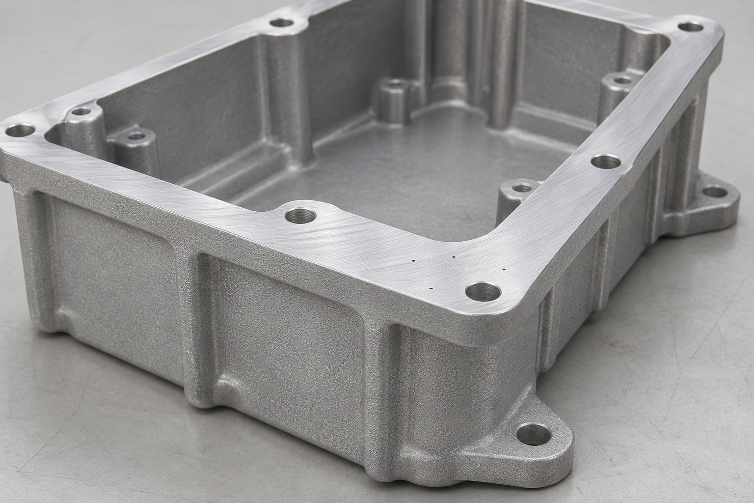
A surface roughness measurement is taken on a very small scale, so contamination has a large effect. Residual cutting fluid, polishing compound, fingerprint oil, or dust can all be registered as part of the profile. Before measuring, clean the surface by an agreed method and handle it in a way that does not add new contamination. A result taken on an unclean surface is not a property of the part.
The environment deserves similar attention for a delicate or coated surface. Vibration, temperature drift, and an unstable support can add noise to a trace. A contact instrument must traverse at a controlled speed with the part held securely; a flexible or thin part may deflect under the stylus and report a surface roughness that reflects the support rather than the surface. Choose a support arrangement appropriate to the geometry.
When two sites compare results, align the cleaning method and the conditioning time. If one party measures immediately after polishing and the other after a cleaning and stabilization step, the surfaces being compared are not the same. A short written instruction covering cleaning, handling, and settling time is often more valuable than a more expensive instrument.
Building a reliable sampling plan
One trace rarely represents a whole surface. Surface roughness can vary across a machined face because of tool path, cutter entry and exit, corners, and clamping. A sampling plan states where and how many traces are taken, and it should be chosen according to the feature and the risk rather than convenience.
- Cover the functional zone. Sample the area that performs the function, not an easy adjacent flat.
- Include known variation points. If a surface has a tool-exit region or a change in direction, decide in advance whether it belongs in the assessment.
- Avoid averaging away a real defect. If one location is clearly worse, record it and investigate rather than folding it into a mean.
- Keep the plan repeatable. Mark or describe locations so a second inspector can measure the same spots.
A documented sampling plan turns a surface roughness result into evidence that can be repeated. Without it, two inspectors can measure the same part, follow the same general instruction, and still produce numbers that appear to conflict. The disagreement is in the plan, not necessarily in the surface.
Correlating contact and optical methods
Contact stylus instruments are widely understood and traceable, but they touch the surface and can be limited by access, sharp edges, or soft coatings. Optical methods avoid contact and can capture an area quickly, but they depend on reflectivity, slope, and surface finish characteristics. Neither method gives a universal answer for every surface roughness question.
If a supplier uses a contact instrument and a customer uses an optical one, agree on a correlation exercise before the results are used for acceptance. Measure the same reference surfaces with both methods over the range of interest and document where they agree and where they diverge. A correlation built on a single sample is rarely enough; surfaces with different textures can behave differently.
Be cautious about converting between profile and areal parameters. Similar names do not guarantee comparable definitions, and a numerical conversion found in a brochure is not a substitute for a measured relationship on the actual surface. When a drawing specifies surface roughness, the most reliable path is to measure the specified parameter with a suitable method under the stated standard.
Recording the result so it can be defended
A surface roughness value on its own is hard to defend if the measurement is questioned later. A useful record identifies the part and drawing revision, the specific surface or marked location, the parameter and units, the standard and edition, the instrument and its calibration state, the filtering and evaluation settings, the trace direction, the sampling locations, and the condition of the surface when measured. That list looks long, but most of it is fixed for a given feature and can be captured once in the inspection instruction.
The record should also state the acceptance limit and the decision rule for a borderline result. If the measured value sits close to the limit, measurement uncertainty matters, and the two parties should have agreed in advance how such a result is handled. Deciding the rule after seeing the number is how a technical check becomes a negotiation.
For a disputed part, keep the original trace and settings rather than only the final number. A profile trace lets a reviewer see whether a single defect dominated the result or whether the surface was uniformly out of range. That distinction often changes the disposition: an isolated mark may be locally polished and rechecked under an agreed rule, while a systematic deviation points to a process change. Preserve the evidence before any rework, because rework removes the condition that caused the disagreement.
Finally, tie the surface roughness record to the process stage. A result taken before finishing is evidence about the substrate; the same number after finishing is evidence about the working surface. Label the stage clearly in the report so that a passing substrate check is never presented as proof of the final surface, and vice versa. A few extra words in the record prevent an entire class of misunderstanding.
What to send with a roughness-sensitive RFQ
Include the drawing revision, material and condition, finishing route, identified functional and cosmetic areas, applicable surface roughness specification, and final inspection requirements. Call out any requirement that applies before finishing separately. If a critical surface cannot be reached by the planned instrument, flag that at quotation stage.
For a CNC machining project review, send YUEYI the model, drawing, quantity, and finishing requirements. Ask for the proposed inspection sequence and any assumptions to be stated in the quotation. For related size and fit decisions, review how tolerances connect to fit and function. Clear inputs are what make a surface roughness result reproducible on both sides.
Technical references and scope
- Mitutoyo: Surface Roughness Measurement — measurement profiles, filtering, stylus effects, and the distinction between texture and imperfections. This educational bulletin references older standards; use the standard and edition specified for the actual part.
- KEYENCE: What Does Surface Roughness Really Tell You About a Part? — measurement comparability and application-specific interpretation.
The inspection planning steps above are a general framework, not a replacement for the drawing or its referenced standard. Inspection examples in this article are hypothetical planning examples, not YUEYI test results.
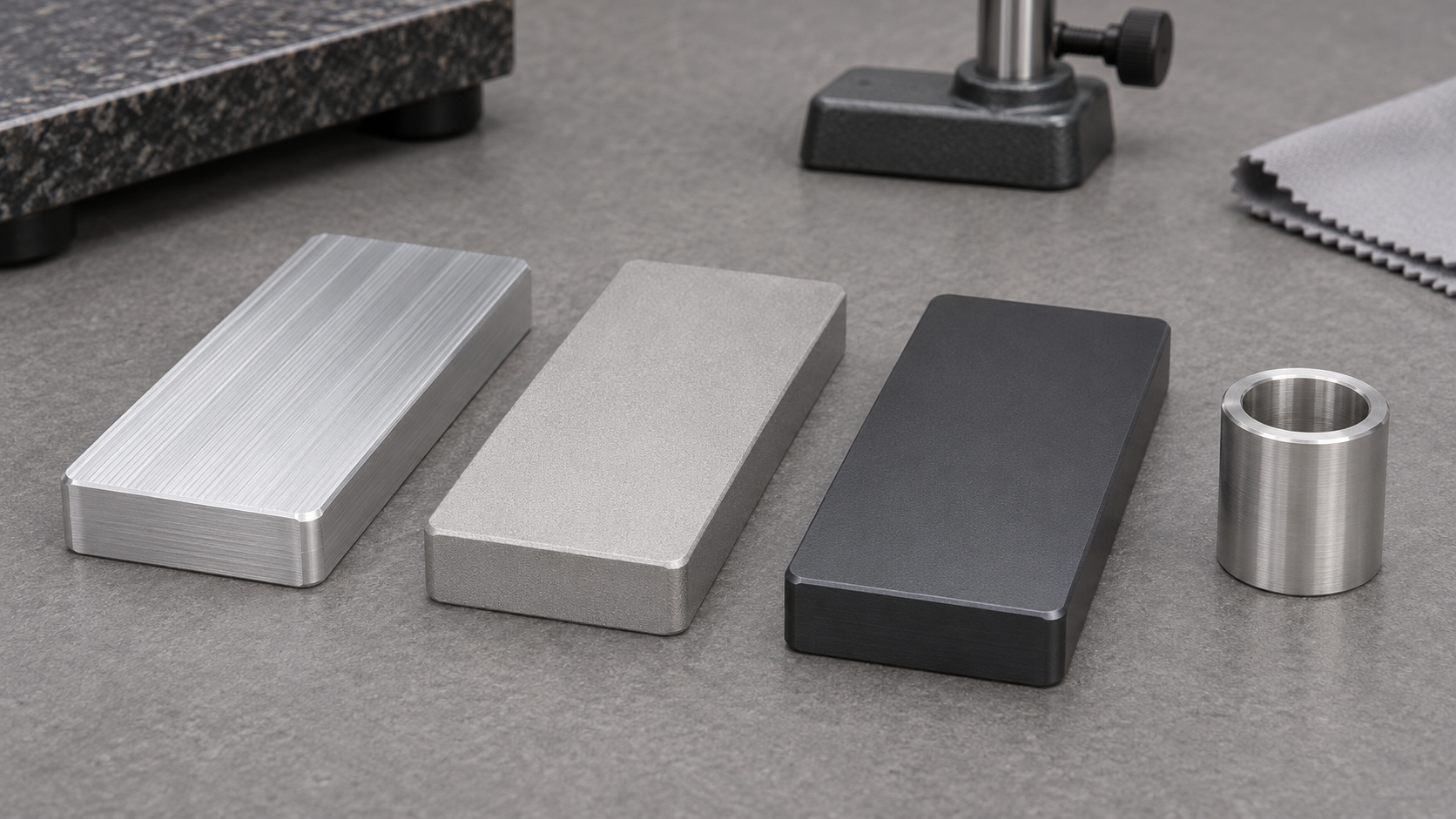
Cover image: illustrative visualization of metal surface textures; not a photograph of YUEYI production or a measurement result.