
In a stepped shaft drawing, a turned shaft can pass a diameter check and still cause trouble during assembly. The bearing may locate against the wrong shoulder, two seats may not run together as intended, or a finishing allowance may be left on a surface that should already be complete. These problems begin with an unclear definition of what the shaft must do.
Before asking a shaft machining supplier to quote, mark the features that support, locate, seal, or transmit load. Then decide how each requirement will be checked. A useful drawing gives the machinist and inspector the same understanding of the finished part.

A stepped shaft drawing starts with the assembly, not the diameter
List what connects to the shaft: bearings, seals, hubs, couplings, gears, or retaining components. Their requirements may apply to different surfaces. A bearing seat supports a ring; a shoulder locates it axially; a seal runs on a separate counterface. Treating all three as one general “precision surface” leaves important decisions open.
In a stepped shaft drawing, use the selected bearing and seal manufacturers’ application guidance when defining their interfaces. A fit suitable for one load, speed, temperature, or bearing arrangement is not automatically suitable for another. Do not copy a tolerance class from a similar-looking shaft without checking the assembly conditions.
Keep size, form and alignment separate on a stepped shaft drawing
On a stepped shaft drawing, size describes the permitted diameter. Form concerns the shape of a feature. A relationship between features needs its own definition where function requires it. Tightening a diameter alone does not completely define how two bearing seats relate to one another.
SKF’s guidance on bearing interfaces discusses dimensional and geometrical seat accuracy separately, along with surface texture. The practical drawing lesson is to identify the specific requirement rather than relying on a single claim that a shaft is “high precision.”
| Feature | Question for the drawing review | Inspection planning input |
|---|---|---|
| Bearing seat | Which bearing and operating conditions determine the interface? | Finished diameter, relevant form requirements, surface condition, and inspection stage. |
| Locating shoulder | Which component contacts it, and what establishes axial position? | Reference features and the required face relationship. |
| Second seat | What relationship to the locating features controls assembly? | Datum references, setup, and the characteristic being evaluated. |
| Seal counterface | What does the selected seal require? | Surface specification and method appropriate to that seal application. |
Define the reference features before choosing a gauge
In a stepped shaft drawing, state which features establish’s reference system. A convenient chucking surface is not necessarily the functional reference. Where a shaft will be inspected between centers, in a fixture, or relative to selected seats, agree how that setup relates to the drawing requirement.
A diameter measurement and a runout check answer different questions. Record the required characteristic, the reference, and the method. If the drawing uses a standard-specific geometrical control, retain that control and its applicable standard; do not replace it with an informal description during quotation.
Make the finished condition unambiguous
Identify dimensions that apply after heat treatment, coating, polishing, or another specified operation. Clarify whether critical seats are protected, finish-machined later, or supplied in an intermediate condition. The supplier should review the proposed sequence before committing to the requirement.
Show thread specifications, reliefs, edge conditions, and surfaces that must remain undamaged during handling. Avoid leaving a critical shoulder transition to a general deburring note when the mating component needs a defined clearance.
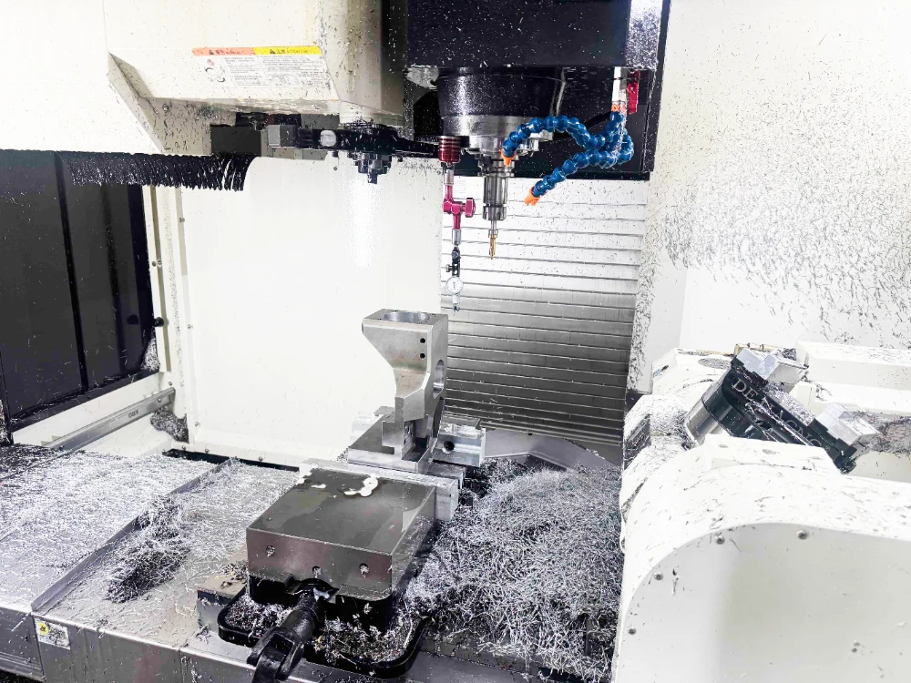
Send a reviewable shaft machining enquiry
- Current model and drawing revision, with units and material grade/condition.
- Assembly interfaces, critical seats, locating features, and relevant mating-part information.
- Required quantity, finishing condition, and delivery request.
- Inspection characteristics, report requirements, and acceptance criteria.
For a China shaft machining supplier, the most useful first discussion is about these requirements. A machine list alone cannot show whether the finished shaft will satisfy your assembly.
Related reading: CNC machining tolerances for fit and function and turn-milling services.
Technical reference
SKF: Design considerations — accuracy of seats and abutments. Application recommendations must be checked against the selected bearing arrangement; this article does not prescribe universal fit or roughness values.
Why a good shaft still fails at assembly
A turned shaft can pass a diameter check and still cause trouble when it is assembled. A bearing may locate correctly on one shoulder and bind against another. A seal may slide over a chamfer that is too sharp and lose its lip. A keyway may sit at the wrong angle to a mating part even though every individual dimension is in tolerance. These are relationship problems, and a stepped shaft drawing has to express them if the supplier is to control them.
This is why the first question on a drawing review should be what the part does in the assembly. Identify which surfaces carry bearings, which locate axially, which seal and which transmit torque. Then decide how each will be controlled and measured. A diameter without a functional reason may be a free dimension; a shoulder with a tight face runout may be critical. Treating every number as equally important obscures the ones that matter.
A supplier who understands the function can suggest a process that protects it. A supplier who sees only a list of diameters will choose a sequence based on convenience and may make the part in an order that damages a critical relationship. A short note about the assembly is often more useful than an additional tolerance.
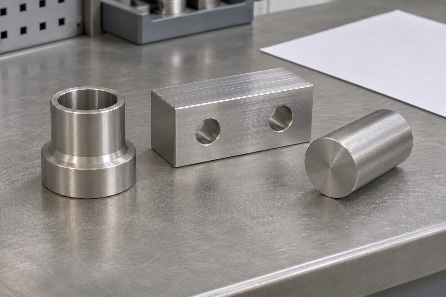
Bearing seats, shoulders and fillets
A bearing seat is defined by more than its nominal diameter. The fit depends on the tolerance, the roundness and cylindricity of the seat, and the condition of the shoulder against which the bearing locates. If the shoulder face is not perpendicular to the axis, the bearing can tilt and carry load unevenly. A stepped shaft drawing should state these requirements where they matter, using the bearing manufacturer’s guidance as a basis rather than a generic table.
Shoulder fillets need similar attention. A larger radius may be needed for fatigue strength, but it can interfere with the bearing chamfer. The drawing should show the radius and the corner condition clearly, and the machining process must be able to produce it. A corner cut with the wrong insert may look correct and still leave a sharp transition that reduces life.
Relief grooves and thread runouts also belong on the drawing. They affect where a mating part can seat and where a tool can finish its cut. If these details are left to the shop, different suppliers will interpret them differently, and the parts may not assemble interchangeably. Defining them once avoids repeated clarification on every order.
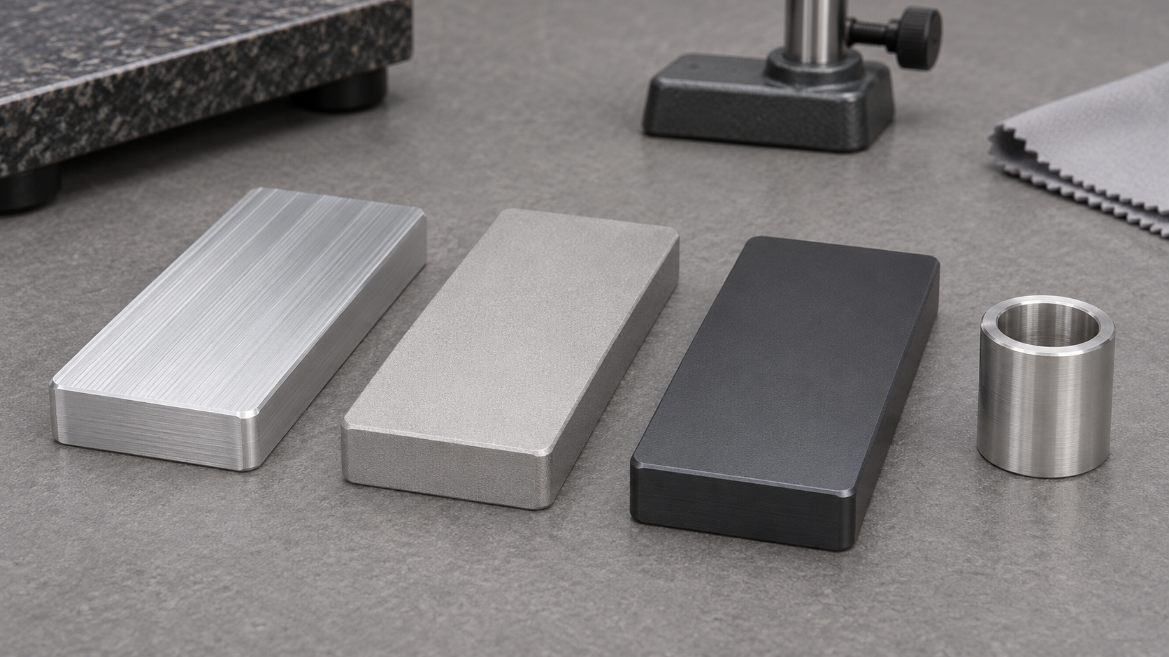
Datums and inspection method
A datum is a reference used to establish a relationship. On a stepped shaft drawing, the natural datum is often a bearing seat or a shoulder face, because that is how the part locates in service. A convenient surface for holding in a chuck is not necessarily the right datum. Choosing the datum from the function makes the inspection meaningful and gives the supplier a stable basis for the process.
Size, form and position are different characteristics. A diameter can be within tolerance while the journal is out of round or the shoulder runs out relative to the axis. State which characteristics are controlled and how they are measured. A runout check and a diameter check answer different questions, and one cannot replace the other.
Decide which measurements are taken before and after heat treatment, coating or polishing. A surface that is finished last must be measured in its final condition. If a process adds material, state whether the dimension applies before or after it. Recording the stage removes the ambiguity that lets two parties measure the same part and report different results.

Making the enquiry reviewable
The most useful enquiry includes the model, the current drawing revision, the material and condition, the quantity, the critical features and the inspection required. State whether alternatives may be proposed and who must approve them. For a fit and function review, mark the features that control assembly. Then send YUEYI the drawing and ask for the proposed process and inspection sequence before the first cut.
Material condition and heat treatment on a stepped shaft drawing
The material condition behind a stepped shaft drawing affects both the process and the final dimensions. Hot-rolled bar may carry scale and a decarburised skin that must be removed before a bearing seat can be finished. Cold-drawn stock starts closer to size but may hold residual stress that is released when shoulders are cut. If a large diameter is removed on one side of the shaft, the part can bend toward the lighter section.
Heat treatment changes dimensions as well as properties. A shaft that is hardened after turning will move, so bearing seats and threads often need finishing afterward. The drawing should say which dimensions apply in the final condition and whether a finishing operation is expected after heat treatment. A stepped shaft drawing that leaves this open invites two suppliers to quote two different routes.
Ask the supplier to state the sequence they assume: rough turning, heat treatment, stress relief if needed, and final machining. For a critical part, request a first article measured after the last operation that affects each feature. This ensures that the inspection reflects the delivered shaft rather than an intermediate state that later processing will change.
Common drawing mistakes and how to avoid them
One common mistake on a stepped shaft drawing is to tolerance every diameter tightly without identifying the controlling relationships. This raises cost and still leaves the critical features uncontrolled if form and position are not stated. A better approach is to define the bearing seats, shoulders and datums precisely and allow sensible generality elsewhere. The result is cheaper to make and easier to inspect.
Another mistake is a missing edge condition. A sharp corner at a shoulder may be impossible to produce reliably and can damage a bearing during assembly. A chamfer or radius that is not drawn will be chosen by the shop, and that choice may not suit the mating part. Show the edge condition where it matters, particularly at lead-ins, shoulders and thread starts.
A third mistake is inconsistency between the drawing and the model. If the model shows a fillet that the drawing does not, or a thread that the drawing omits, the supplier must guess which controls. State which document governs and keep both at the same revision. A short note prevents a disagreement that would otherwise surface only when parts do not assemble.
Keys, threads and secondary features
A stepped shaft often carries a keyway, a retaining groove or a radial thread in addition to its turned diameters. These secondary features introduce another setup or a live-tool operation and can affect the relationships the drawing controls. A keyway must be positioned relative to a bore or another keyway if torque is transmitted through more than one point. State that angular relationship rather than letting the shop choose a convenient orientation.
Threads on a shaft need a defined fit and a defined stage of inspection. If the part is plated after machining, the coating shifts the effective thread size. Decide whether the thread is masked, cut after coating or allowed for in the machining dimension, and specify the gauge that applies to the delivered part. A stepped shaft drawing that simply notes a thread without this detail leaves a common source of assembly problems unresolved.
Retaining grooves concentrate stress and need a defined radius and width. A groove that is too sharp can start a fatigue crack, while one that is too wide may not locate the ring correctly. Use the ring manufacturer’s guidance for the groove and confirm that the cutting tool can produce the specified form. These small features often decide whether a shaft survives its service life.
From drawing review to first article
A useful first article for a stepped shaft reports each controlled diameter, the form of the bearing seats, the shoulder positions and the relationships between features. It should state the datum used for each measurement and the point in the process when it was taken. A report that lists numbers without these details cannot be compared with a later batch or with a supplier’s own records.
Ask how the part was held for machining and for inspection. A shaft supported between centres can measure differently from one held in a chuck, particularly if it is long or slender. If the drawing assumes a free-state condition, the inspection setup should not impose a restraint that hides movement. Matching the measurement to the drawing intent is as important as the instrument used.
Keep the drawing, the material certificate, the process sequence and the inspection results together. When a later order differs, that package shows whether the change came from material, setup or measurement. A stepped shaft drawing supported by a complete record becomes a repeatable product rather than a one-off success, and future quotations can be compared on the same basis.
Using the stepped shaft drawing as a shared control document
A stepped shaft drawing is not only a manufacturing instruction; it is the reference that keeps the buyer, the supplier and the inspector aligned. When a stepped shaft drawing is clear about function, a quotation reflects the real work and later changes can be traced to a reason. When the stepped shaft drawing is vague, each party fills the gaps differently and the first article becomes a negotiation rather than a check.
Treat every revision of the stepped shaft drawing as a controlled document. Record who approved the stepped shaft drawing, which features are critical and which requirements were relaxed or added. A stepped shaft drawing that carries this history lets a repeat order be quoted against the same basis. It also lets a new supplier understand the intent of the stepped shaft drawing without relearning it through trial parts.
Used this way, the stepped shaft drawing becomes the link between design intent and measured result. Keeping the drawing, the process sequence and the inspection record together means a stepped shaft drawing can be reviewed, repeated and improved without losing the decisions behind it. For a machined component, the drawing is also a record of the choices that could not be shown as a dimension alone. A note about the assembly, a chosen datum or a required inspection stage may matter as much as a tolerance, and each belongs in the controlled stepped shaft drawing.