
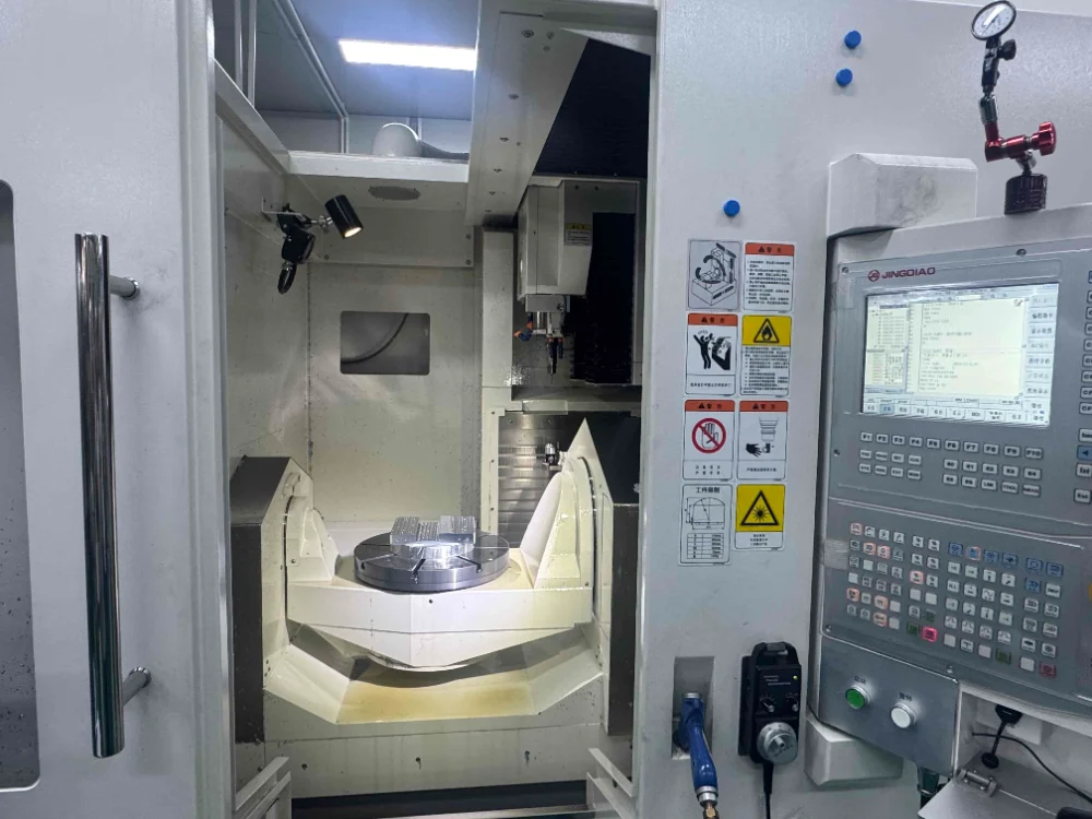
A housing with holes on four faces does not automatically need simultaneous 5-axis machining. 5-axis machining. The useful question is how to reach those features while holding the part securely and preserving the relationships that matter in assembly. For multi-face CNC parts, choosing a process starts with the drawing and the proposed setups.
This review of 5-axis machining helps engineers compare conventional setups, indexed machining, and simultaneous motion. It also gives buyers practical questions to ask a 5-axis machining supplier before accepting a quotation.

5-axis machining: distinguish the method from the machine label
In indexed 3+2 5-axis machining, rotary axes orient the workpiece or tool for a cutting operation; the operation then uses the linear axes at that orientation. Simultaneous 5-axis machining coordinates linear and rotary movement during cutting. A part with features on several sides may use indexed operations without needing continuous rotary motion throughout the cut.
Confirm the proposed 5-axis machining method for the actual features. Do not treat a machine photograph as proof of a particular toolpath, finished tolerance, or inspection result. Our introduction to CNC machine axes covers the basic terminology; the checks below concern process planning.
5-axis machining: check access with holder and fixture included
A cutter may appear to reach a pocket in the CAD model while its holder conflicts with a wall or clamp. Review the complete cutting assembly, the approach direction, and the available clearance. A long tool extension may solve one interference while creating another planning constraint.
Haas’s 5-axis planning guide recommends short tools and checking clearance when the workpiece is indexed. Those are useful review prompts, not universal settings for your part. The programmer must evaluate the intended tool, fixture, stock, and machine configuration.
For 5-axis machining of an angled hole or recessed face, ask which orientation provides access. For a contoured surface, ask whether changing tool orientation during the cut is necessary. Avoid prescribing simultaneous motion simply because the finished component looks complex.
Identify what remains clamped
For 5-axis machining, mark the surfaces available for gripping and those that will become finished interfaces. Ask how the first setup establishes references, how the remaining clamped area is completed, and whether another setup is needed. A five-sided operation does not automatically finish the sixth side.
| Part feature | Review question | Information needed |
|---|---|---|
| Holes on several faces | Can indexed positions reach each feature? | Hole directions, depths, access, and position requirements. |
| Deep pocket | What clears the wall and fixture? | Tool and holder geometry, pocket depth, corner geometry. |
| Thin wall | How is the wall supported during cutting? | Stock condition, support areas, machining sequence. |
| Mating faces | Which relationships control assembly? | Controlled drawing, datum references, acceptance criteria. |
| Clamped underside | How will the final holding area be completed? | Second-operation plan and reference transfer. |
Keep feature relationships visible in the review
For 5-axis machining, list the bores, mounting faces and hole patterns that work together. Finishing related features in fewer setups can reduce reference transfers, but it does not remove the need to control workholding, tool behavior, and inspection. A machine’s positioning specification is not a finished-part tolerance guarantee.
Use the drawing’s actual controls. If a bore location is important relative to a mounting face, checking the bore diameter alone will not verify that relationship. See our guide to tolerances for fit and function for this distinction.
Agree the inspection plan before comparing routes
Ask how critical characteristics will be measured after 5-axis machining after machining and any specified finishing. Identify the reference setup, report scope, and any features that are difficult to access. An on-machine check can support process control; clarify separately what evidence will accompany the delivered parts.
Compare quotations using the same revision, material, quantity, finish, and inspection scope. Programming and fixture work may be distributed differently between setup charges and unit prices. Evaluate the proposed delivered result rather than selecting a route by axis count alone.
Technical reference
Haas Automation: 5-Axis Simplified. Manufacturer planning guidance is used as a reference; its machine specifications are not YUEYI capability claims.
When 5-axis machining earns its cost
Five-axis equipment adds cost through programming, setup and machine time. It earns that cost when it solves a problem that a simpler route cannot: access to several faces without repeated reclamping, a contoured surface that must be cut in one continuous path, or a set of features whose relationships depend on being made in one setup. A part with holes on four flat faces may be faster and cheaper on a three-axis machine with a rotary table, even though the machine is technically capable of five-axis work.
The useful question is not whether the part can be made on a five-axis machine, but what that choice controls. If a bore must hold a tight position relative to a face on the opposite side, making both in one clamping can remove a source of error. If the tolerances are generous and the faces are accessible, indexed setups on a simpler machine may be equally accurate. Decide which relationships justify the extra setup before choosing the process.
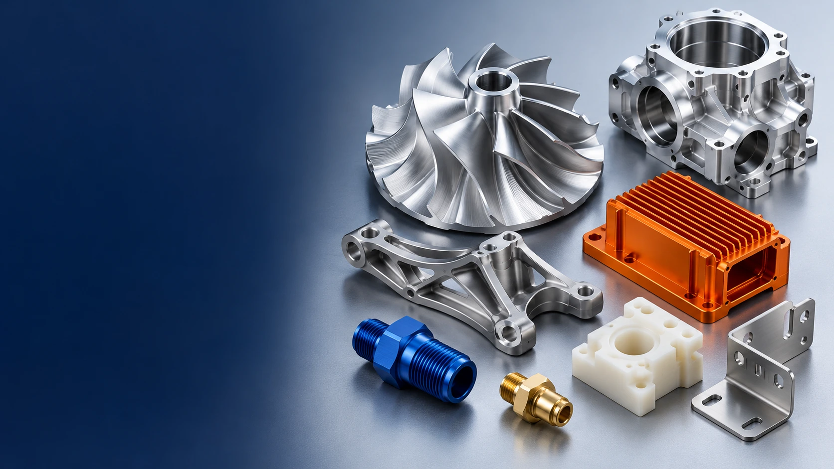
Simultaneous five-axis motion is different from indexed 3+2 work. In indexed machining, the rotary axes position the part and the cut is made with a fixed orientation; it is often faster and easier to program. Simultaneous motion is reserved for toolpaths that must change orientation during the cut, such as impeller blades or complex contours. A drawing that says “5-axis” without saying which mode is meant leaves the method open to interpretation.
Access, tool holding and collision checks
A cutter may appear to reach a pocket in the CAD model while its holder conflicts with a wall or clamp in the real setup. In 5-axis machining, the tilted tool and the rotary table change the collision picture completely. Check clearance with the actual tool holder, gauge length and fixture, not just the cutting tool. A path that is valid for the tip can be impossible for the holder.
Short tools are usually preferred because they deflect less, but they may not reach a deep recess. The programmer has to balance reach against rigidity. A long, slender tool can produce a surface that looks acceptable while leaving a form error that appears only in inspection. Where reach is unavoidable, reduce the cutting load and verify the result on a representative part before the batch.
Fixture design is part of the access review. A clamp that is convenient for a three-axis setup may block the rotary motion or the tool approach in five-axis work. Involve the fixture designer when the process is chosen, and confirm that the part can be loaded and unloaded safely in the intended orientation. A collision-free toolpath is of little use if the part cannot be clamped as programmed.
Holding the part and preserving relationships
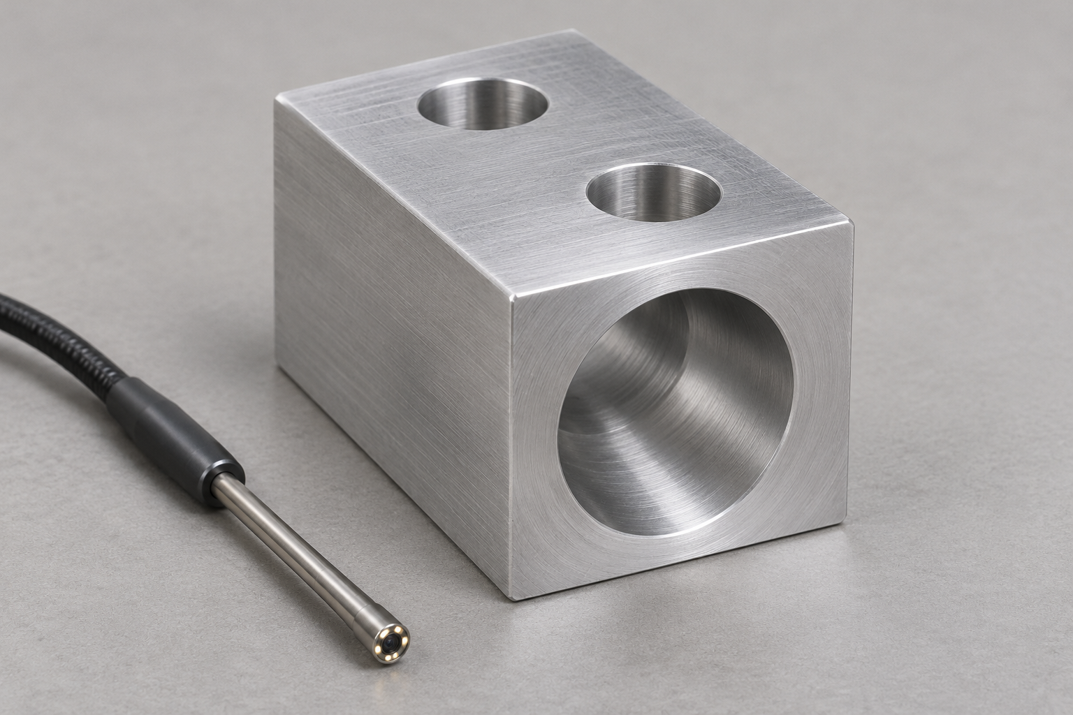
Every time a part is removed and re-clamped, there is a chance that its position changes relative to the tool. For 5-axis machining of multi-face parts, one setup can preserve relationships between faces, bores and patterns that would be at risk across several setups. That benefit is strongest when the drawing controls those relationships tightly. Where controls are loose, the benefit is smaller and may not justify the cost.
One setup is not automatically more accurate. If the part is held on a surface that will be removed early, or if the clamp distorts a thin section, the finished geometry can be wrong in a way that a second setup would have avoided. Identify which surfaces are available for gripping and which become finished interfaces. Choose locators that will remain stable through the operations that matter.
Ask what remains clamped between operations. A process that appears to be one setup but releases the part for inspection midway introduces a re-location step. If that step is necessary, define how the part is relocated and which features are used. Keeping the datum chain visible makes it possible to judge whether 5-axis machining is genuinely protecting the relationships the drawing requires.

Inspection and quoting on a common basis
Agree how critical characteristics will be measured after machining and any finishing. A feature made in one setup still needs a defined datum and method in inspection. If a bore position is controlled relative to a mounting face, the measurement must reference that face in the same way the drawing intends. A number reported against a convenient but unrelated surface cannot settle a dispute.
When comparing quotations, use the same drawing revision, material, quantity, finish and inspection scope. One supplier may have assumed indexed machining and another simultaneous motion, which changes the price and possibly the achieved relationships. Ask each supplier to state the method and the setup count so the quotes can be compared on process rather than on a single number.
For a drawing review or a CNC machining project, send the model, the drawing with critical features marked and the inspection requirements. Review fit and function, then ask YUEYI to review the route before committing to a process.
Programming and verification before cutting
A five-axis program needs more verification than a simple three-axis toolpath because the machine can put the tool and the part in many more relative positions. Simulation should include the machine, the holder, the fixture and the stock, not only the cutter. A path that is collision-free in a generic CAM check can still fail on a particular machine with a different table or trunnion. Verify against the actual setup that will run the part.
Dry runs and single-block checks are useful on a new setup, particularly during the first article. They confirm that the rotary moves behave as programmed and that the machine does not approach a limit at an awkward orientation. A program that works at the centre of the table may behave differently near the edge, so check the real position of the part.
Post-processor choice matters. A generic post can produce code that runs but uses unnecessary moves, unusual feed behaviour or unsafe rapids. Confirm that the post matches the machine and the controller revision. When 5-axis machining is quoted by more than one supplier, ask what verification each performs; the difference is often reflected in the reliability of the first article rather than in the cycle time alone.
Workholding for rotary setups
A rotary table changes how a part must be held. The clamp must resist not only cutting force but also gravity as the part turns, and it must not interfere with the machine’s travel. A fixture that is perfectly safe in an upright position can become a collision risk when the table tilts. Check the swept envelope before committing to a design.
Balance matters at higher rotary speeds. An unevenly loaded table can reduce accuracy and place avoidable load on the machine. Where a part is light and the cuts are modest, this is a minor concern; where heavier stock is removed, the distribution of mass affects how the axis behaves. Ask the supplier how the setup is balanced, especially if a long cycle is expected.
Torque and access compete. A part held with a light touch may move under a heavy cut, while a heavily clamped thin wall may distort. Choose locators and clamps that support the part near the cutting zone, and confirm that the tool can still reach the required features. For 5-axis machining of a difficult geometry, the fixture is often as important as the machine itself.
Choosing between indexed and simultaneous work
Indexed 3+2 positioning suits many multi-face parts. The rotary axes orient the part, the tool cuts with a fixed axis, and the setup is comparatively easy to program and inspect. If the features are planes, holes and pockets on several faces, this approach may deliver the required relationships with less cost than continuous five-axis motion. It should be considered before assuming that simultaneous movement is necessary.
Simultaneous motion earns its place when the tool must follow a changing orientation through the cut: a contoured blade, a complex fillet or a surface that cannot be reached in a fixed orientation. These toolpaths are harder to program and verify, and they place higher demands on the machine and the fixture. They are justified when the geometry truly requires them, not because the shop has the capability.
A useful review asks which feature drives the choice. If the answer is a single angled face, an indexed setup is usually enough. If it is a freeform surface that must blend into several faces, simultaneous motion may be the only practical route. State the reason in the process plan so the decision can be revisited when the design or quantity changes.
From review to a comparable quotation
Before requesting quotes, mark the features whose relationships matter and identify the faces that must be finished. A supplier who understands which features are critical can propose a setup that protects them. A supplier who receives only a model and a quantity will choose the cheapest apparent route, which may not preserve the relationships the design depends on.
Ask each bidder to describe the setup count, the method, the inspection plan and any assumptions about workholding. Two quotations that look far apart may simply assume different processes. Comparing them on process makes the difference visible and lets the buyer choose between a cheaper route with more set-ups and a more expensive one that holds relationships in a single clamping.
For 5-axis machining of a new part, a first article with staged measurements is worth the cost. Measure the critical relationships after the operations that create them and again after any finishing step. Keep the records with the drawing revision so a later batch can be compared. A clear baseline turns a difficult process into a controlled one and makes future quoting more reliable.
Documenting the 5-axis machining decision
Whatever route is chosen, record why. Note which features drove the decision, which setup count was assumed and what inspection was agreed. A short process note makes the choice defensible when a later order is quoted by a different person or a different supplier. When 5-axis machining was selected to protect a relationship, say which relationship it protects so the next review does not drop it as an unnecessary cost.
Review the decision when the design, quantity or finish changes. A part that justified one setup at low volume may be better suited to indexed machining at higher volume, or the reverse may be true if a new tolerance is added. Treating the first process choice as permanent is how costs drift and relationships slowly lose control.