
A bore meets its diameter requirement, but its position relative to the outside of a die-cast housing changes between parts. Before adjusting the machining program, check how each casting sits in the fixture. In die casting machining datums, a drafted wall, a parting-line witness or an inconsistently trimmed area can make a seemingly convenient locating surface unsuitable for the intended setup. This article sets out the review questions that connect the casting drawing, the fixture, and finished-part inspection.
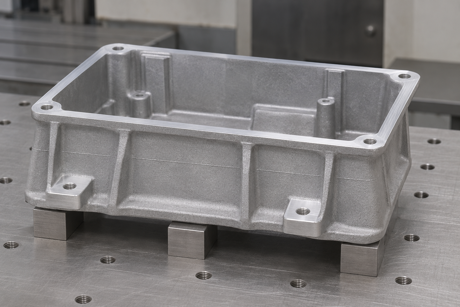
For die casting machining datums, start with the relationship the assembly actually needs. Identify the finished functional references, then review how the first machining operation will locate the raw casting and create those references. The following review questions help connect the casting drawing, fixture and finished-part inspection; they are not a prescribed fixture design. They are a way to make die casting machining datums a deliberate decision rather than an accident of clamping.
Separate the cast shape from the finished references
In die casting machining datums, draft is the taper provided to help release a casting from the die. A side wall that looks square in an illustration may be intentionally sloped in the casting model. A datum, by contrast, is a reference used to establish a geometrical relationship. Choosing die casting machining datums requires the drawing’s functional requirements; it cannot be settled by choosing whichever surface is easiest to clamp.
NADCA’s CAD feature-order guidance recommends keeping machining features separable from the cast geometry. That makes it easier to communicate the as-cast and machined configurations and review the stock required for machining. Keep both configurations at the same approved revision so the fixture designer can see what exists before the first cut. A datum that is convenient in the finished model may not exist as a stable surface on the raw casting.
This separation is the foundation of a sound plan for die casting machining datums. The as-cast part and the finished part are two different geometries, and the first operation is the bridge between them. If the bridge is designed around an imaginary surface rather than the real casting, the resulting datum shift will appear as a position error that no program change can reliably fix.
Find out what the fixture actually touches
To verify die casting machining datums, examine a representative casting in the proposed setup. Identify each support, locator and clamp contact. Check for rocking before clamping and whether tightening changes the seating. If a clamp pushes a tapered face against a locator, review whether the resulting contact position is repeatable. Do not infer the contact condition from the finished CAD model alone — the surfaces that locate a raw casting are often as-cast, and their variation directly affects die casting machining datums.
Look specifically at trimmed regions, ejector marks and the parting line. NADCA explains that flash at the die split can affect dimensions measured across that region. Its design guidance recommends considering the die split early with the casting engineer. For machining review, ask whether a locator touches a controlled cast feature or a variable remnant of trimming. A locator resting on a trimmed edge that changes from part to part will move the entire datum system.
| Setup observation | Question to investigate | Evidence to retain |
|---|---|---|
| The casting rocks before clamping | Are the intended supports contacting the casting, or is an unintended high spot carrying it? | Contact locations and the casting identity |
| Position changes after reclamping | Does the locating arrangement reproduce the same seating and orientation? | Repeated setup measurements using an agreed method |
| Machined features align with each other but shift relative to cast walls | Is the first setup or the relationship between cast and finished geometry responsible? | Measurements tied to both configurations |
| A fully machined face has an uncut patch | Was sufficient local stock available in the actual located position? | Stock assessment and the affected location |
These observations guide an investigation. They do not prove a single cause. Casting variation, fixture contact, machining and measurement can contribute to the same symptom, so record them separately rather than changing several variables at once. Changing the program and the locator at the same time destroys the evidence about which one actually controlled die casting machining datums.
Review the first cut and the later setups together
One route is to use agreed cast locating features for the first operation, then locate later operations from the newly machined references. Another is to revise the cast locating features or fixture contact arrangement. Each option needs review against access, available stock, clamping support and the required relationship to unmachined surfaces. The choice determines how die casting machining datums are transferred from the casting to the finished part.
A machined reference does not automatically solve every relationship. If the assembly also depends on an unmachined wall, that wall still needs an appropriate control and inspection plan. Equally, adding machining to every exterior face can add work without addressing the functional requirement. Ask which relationship the proposed extra operation will actually control before adding it to the route.
Identify the intended locating contacts.
Create the agreed machined references.
Verify the functional relationships.
Plan the sequence on paper before cutting metal. A datum transfer scheme that looks logical in a meeting can fail if the first operation cannot actually reach the surfaces it must create. Walk through access, tool approach and clamping for each stage, and confirm that the references created early are available to locate the part later. This is where a review of die casting machining datums usually pays for itself.
Check stock before increasing the machining allowance
To check die casting machining datums, compare the casting and finished models in the proposed setup orientation. Review local stock at faces, bores and bosses, including the variation allowed by the controlled drawings. An allowance that looks sufficient at one section may not cover another location once the casting is located. Stock that is measured in a free state can disappear when the part is clamped according to the real die casting machining datums.
Do not add a universal stock value or remove more metal simply because a surface fails to clean up. That decision can affect wall thickness and the casting design. If machining reveals cavities, investigate that separately using the guide to porosity exposed after machining; extra cutting is not an automatic remedy.
How draft and parting lines move the locating surface
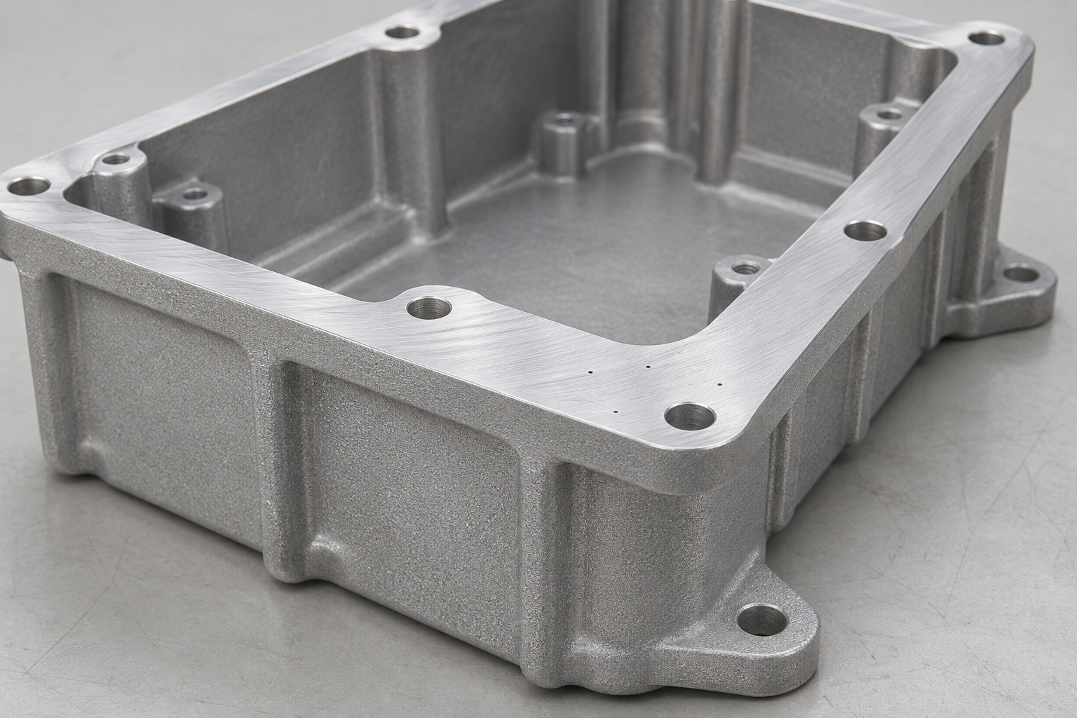
Draft and parting lines are not cosmetic details; they decide where a casting can be held repeatably. A drafted wall presents a different contact height depending on where the locator touches along the slope. A locator placed near the parting line may contact flash on one casting and a clean surface on the next. Both cases shift die casting machining datums without any change to the program or the fixture drawing.
The remedy is to choose locating features whose position is controlled and stable across the production spread. Where the casting design offers no such feature, the discussion belongs with the casting engineer and the fixture designer before production, not after a batch of misplaced bores. Agreeing on dedicated locating pads or a controlled datum target can turn a variable contact into a repeatable one.
Ejector marks and trim remnants deserve the same scrutiny when setting die casting machining datums. A support that lands on an ejector pin witness may see a raised or recessed spot that changes with the die. Identify these features on the casting drawing and keep locators clear of them where possible. If they cannot be avoided, build the variation into the locating scheme rather than assuming a nominal surface.
Make the first-article report answer the setup question
Agree the inspection alignment and required records before the trial. The report should distinguish finished-feature relationships from relationships to the remaining cast surfaces. Record the drawing revisions, setup stage and part identity. Where reloading repeatability is in doubt, agree a suitable repeat-placement check rather than accepting one favorable measurement. A first article that reports only final dimensions cannot explain a problem with die casting machining datums.
Include the contact map in the record: which supports and locators were used, and where they touched the casting. When a later batch drifts, that map lets the team reproduce the original setup and find out whether the contacts changed. Without it, the investigation starts from scratch and often settles on a program adjustment that treats the symptom.
Review any change to a locator, trimming operation or first-cut sequence before treating an earlier approval as representative. The acceptance limits must come from the controlled project requirements. This article supplies no universal draft angle, machining allowance or positional tolerance. Those values depend on the alloy, geometry and the functional requirements of the specific part.
Building a datum plan the whole team can follow
A written plan makes die casting machining datums explicit for everyone who touches the part. It should name the as-cast locating features for the first operation, the machined references that operation creates, and how each later setup locates from those references. It should also identify which relationships are to unmachined surfaces, because those cannot be corrected by adding a machined datum elsewhere.
Keep the plan with the controlled drawings and the fixture documentation, and update it when any locator or process step changes. A plan that lives only in a fixture drawing is easy to miss when the casting revision changes. When the plan, the drawing and the setup agree, a position error becomes a tractable problem rather than a recurring dispute between casting and machining.
Review the plan at three points: after the casting design is released, after the first fixture is built, and after the first article is measured. Each review checks a different assumption. Catching a mismatch at one of those points is far cheaper than reworking a batch of castings whose die casting machining datums were never correctly defined, and it keeps the datum plan honest as the design evolves.
For a project review, send the as-cast and finished models, drawings, critical assembly relationships and the affected inspection results. See die-casting service information and the machining RFQ checklist, then request a drawing review. Flag the features that must remain as cast so their requirements are included in the discussion.
Why a good diameter can still be in the wrong place
In die casting machining datums, a bore that meets its size tolerance can still fail assembly if its axis sits in the wrong location. This is one of the most common reasons a machined casting is accepted at inspection and rejected at fit-up. The diameter check confirms the tool made a hole of the right size; it says nothing about where the casting was held when the hole was cut. That position is governed by die casting machining datums, not by the cutting tool alone.
When a bore shifts between parts while its diameter stays constant, look at the setup before the tool. A constant diameter with a moving position is the signature of a locating problem: the tool followed the same path in machine coordinates, but the casting sat differently on the fixture each time. Adjusting the program will simply move the error to a different average position without making it repeatable.
The opposite pattern is also informative for die casting machining datums. If the position stays stable but the diameter drifts, the cause is more likely tool wear, deflection, or a cutting parameter than the datum system. Reading these two signals separately helps the team focus on the right variable. Confusing them is how a locating problem gets “fixed” with a tool offset that only masks one batch.
Coordinate the casting and machining drawings
Die casting machining datums should be readable on both the as-cast and the finished drawing. If the casting drawing defines one set of features and the machining drawing references another without explaining the link, the fixture designer has to guess how the first operation locates the part. That guess is where datum inconsistency begins. Make the transfer explicit by showing which cast features establish the first setup and which machined surfaces become references afterward.
Revision control matters here because die casting machining datums depend on the casting geometry. A change to the casting can move or remove a locating feature that the machining setup relies on. If the two drawings are at different revisions, the fixture may be designed around a feature that no longer exists. Keep the as-cast and machined configurations at the same approved revision, and review die casting machining datums whenever either drawing changes.

A short datum note on the drawing is often enough to prevent a long dispute. State which surfaces are as-cast, which are machined, and which relationships are functional. The note does not replace a proper tolerance scheme, but it tells everyone how the part is intended to sit through the process. That shared understanding is the practical value of defining die casting machining datums clearly.
Measurement can imitate a datum problem
Before concluding that die casting machining datums are at fault, confirm that the measurement itself is sound. A position result depends on how the part is supported on the measuring table and which surfaces are used to establish the inspection coordinate system. If the inspection setup references a different feature from the machining setup, the reported shift may describe a measurement datum difference rather than a change in the part.
Check that inspection locates the part the same way the assembly does, so die casting machining datums are judged correctly. Measuring a casting on an as-cast surface when the functional relationship is to a machined face can introduce variation that has nothing to do with the machining process. Aligning inspection die casting machining datums with the drawing’s functional references makes the reported position meaningful. A number tied to the wrong reference is worse than no number, because it looks authoritative.
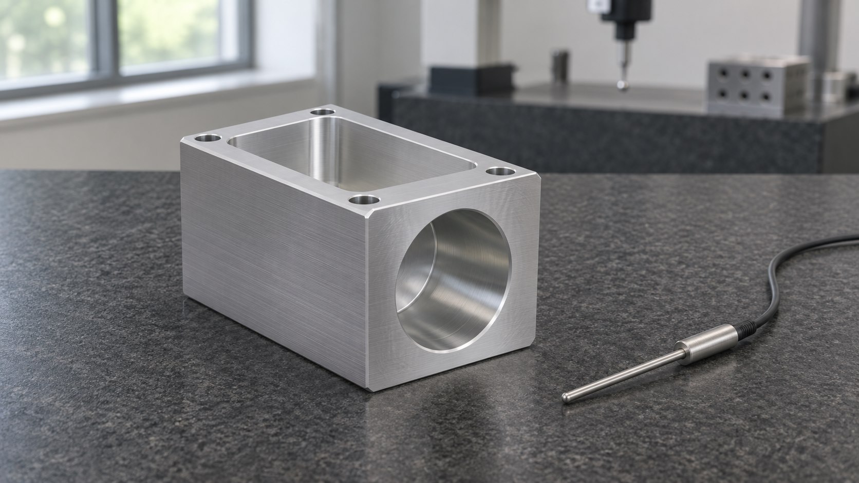
For die casting machining datums, repeatability is the quickest test. Measure the same feature after several placements in the inspection fixture. If the result moves with placement, the measurement setup is contributing variation and should be corrected before anyone changes the machining setup. Only once inspection is stable can it be used to judge whether die casting machining datums are controlling position as intended.
Sources and applicability
- NADCA: Draft — the purpose of taper and why requirements depend on geometry and alloy.
- NADCA: CAD Feature Order — communicating cast and machined configurations and reviewing machining stock.
- NADCA: Parting Line — the die split, flash and dimensional considerations.
- International Zinc Association: Design Rules — zinc-specific guidance on parting lines and draft. Its numerical recommendations are not transferred here to aluminum or another alloy.
The review steps above are a general framework, not a fixture design or a set of universal tolerances. Apply the controlled project requirements and the governing drawing revision to a real setup decision.
Cover: AI-generated illustrative visualization of a cast housing on supports. It is not a YUEYI production sample, fixture qualification or inspection result.